background image

GAM Quick Installation Guide 


Positron Access Solutions 

29 

Document 180-0211-001 R01 

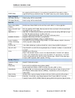
Ease of Operation  

Supports firmware and configuration management of G.hn end-point devices 

Encryption 

AES-128 encryption with individual keys for each End Point. The Positron GAM Domain 
Master is also acting as the G.hn Security Controller 

Modulation and 
Frequency Band 

Supports OFDM 200 MHz. Telephone wiring supports 1 pair (Single Input Single Output - 
SISO) and 2 pairs (Multiple Input Multiple Output - MIMO) per RJ-45 port 
Radio Band Notching function allows cohabitation with legacy analog cable TV channels 
on coax cabling and concurrent use with POTS and DSL on telephone pairs 

Bandwidth 
Management 

Up to 1.7 Gbps with Dynamic Bandwidth Allocation to optimize throughput based on 
nature of traffic flows with TDD Multiplexing for programmable upstream / downstream 
ratio 

Vectoring (Telephone 
Wiring) 

Support for VectorBoost

™ vectoring for FEXT (Far-End Crosstalk) mitigation and 

improved performance over Telephone wiring 

Mitigation of Near-end 
Crosstalk 

Near End Crosstalk (NEXT) Mitigation and support for Neighbor Domain Interface 
Mitigation (NDIM) 

PSD 

Programmable PSD mask for coexistence with xDSL / radio and Far End Crosstalk 
(FEXT) mitigation via VectorBoost

™ vectoring 

Reliability and 
Resiliency 

State of the art LDPC Forward Error Correction (FEC) 

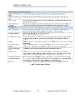
Layer 2 Switching 


Spanning Tree Protocol 
(STP)


Standard Spanning Tree 802.1d 


Rapid Spanning Tree (RSTP) 802.1w 


Multiple Spanning Tree (MSTP) 802.1s


MAC Table 

Up to 32K MAC addresses 

Trunking


Link Aggregation Control Protocol (LACP) IEEE 802.3ad for any SFP+ or G.hn ports


VLAN


Supports up to 4K VLANs simultaneously (out of 4096 VLAN IDs) 


Port-based VLAN


IEEE 802.1Q tag-based VLAN


IEEE 802.1ad (Q-in-Q) double tag VLAN


MAC-based VLAN


Management VLAN


Private VLAN Edge (PVE)


Generic VLAN 
Registration (GVRP)


Protocols for automatically propagating and configuring VLANs in a Multicast Domain for 
IPTV and other multicast services


IGMP v1/v2/v3 
snooping


IGMP limits bandwidth-intensive multicast traffic to only the requesters 
Supports 1024 multicast groups


IGMP Proxy


IGMP snooping with proxy reporting or report suppression actively filters IGMP packets to 
reduce load on the multicast router


IGMP Query 

IGMP query is used to support layer-2 multicast domain in the absence of a multicast 
router 

MLD v1/v2 snooping


Deliver IPv6 multicast packets only to the required receivers


DHCP Server 

Supports DHCP server to assign addresses to IPv4 client devices 

DHCP Snooping


DHCP snooping provides security by filtering un-trusted DHCP messages and by building 
and maintaining a DHCP snooping binding table


Summary of Contents for GAM-4-MRX

Page 1: ...G hn Access Multiplexer GAM Quick Installation Guide GAM 8 MX GAM 4 MX ...

Page 2: ...By Positron Access Solutions 5101 Buchan Street Suite 220 Montreal Quebec Canada H4P 2R9 Telephone US and Canada 1 888 577 5254 International 1 514 345 2220 Product names other than Positron s mentioned herein may be trademarks and or registered trademarks their respective companies Disclaimer Notice Although Positron Access Solutions has made every effort to ensure the accuracy of the information...

Page 3: ...rts 8 1 2 5 GAM LED Indicators 10 1 2 6 GAM Reset Button 12 Chapter 2 14 Step by Step Installation 14 2 1 Step by Step Installation Procedure 15 Chapter 3 24 WEB Management 24 3 1 Introduction 25 3 2 System Management 25 3 2 1 Logging into the WEB GUI 25 3 2 2 System 26 3 2 3 General Information 26 Chapter 4 27 Technical Specifications 27 4 1 GAM Technical Specifications 28 Chapter 4 32 Safety and...

Page 4: ... CORNER OF THE GAM CIRCUITRY 9 FIGURE 5 GAM SERIAL MANAGEMENT PORT PINOUT 9 FIGURE 6 GAM GLOBAL STATUS LEDS 10 FIGURE 7 G HN PORTS LEDS 11 FIGURE 8 SFP LED 12 FIGURE 9 GAM RESET RST BUTTON 13 FIGURE 10 GAM LOGIN PAGE BROWSER SPECIFIC 25 FIGURE 11 GAM PORT STATUS PAGE DEFAULT PAGE AFTER LOGIN 26 List of Tables TABLE 1 GAM GLOBAL LED INDICATORS 10 TABLE 2 G HN PORTS LED INDICATORS 11 TABLE 3 SFP LED...

Page 5: ...GAM Quick Installation Guide Positron Access Solutions 5 Document 180 0211 001 R01 Chapter 1 ______________________________________ About the GAM ...

Page 6: ...with in building fiber installation G hn is an Access technology for Operators looking to simplify their access network and backend infrastructure with an Ethernet like technology that is highly scalable without some of the inherent complexity of DSL related technologies With G hn Operators deliver advanced services such as Gigabit High Speed Residential Internet and 4K IPTV without the high capit...

Page 7: ...owered If you need a Reverse Powered Fed RPF GAM please refer to the GAM 4 MRX or GAM 8 MRX products Figure 1 GAM Power Input Connector 1 2 2 Ethernet SFP Port Figure 2 GAM SFP Connectors The GAM has one 1 SFP ports that support any MSA compliant SFP SFP modules Fiber 1G 10G and Copper RJ 45 100M 1G Important note When connecting the SFP port to a Passive Optical Network PON fiber connection pleas...

Page 8: ...ngle pair SISO mode or two 2 pairs MIMO mode per port The 110 Punch down blocks are located at the top left portion inside the GAM IP67 enclosure Note fast and resettable lightning protection is pre installed on the GAM motherboard for each copper pair Figure 3 Inside view of GAM 8 MX with 110 Punch down Block 1 2 4 Local management ports The GAM devices have two 2 local management ports located n...

Page 9: ...ss to the command line interface of the GAM device The pinout of the RJ 45 serial port is compatible with the popular Cisco pinout as per the following diagram Figure 5 GAM Serial Management Port pinout The MGMT port is a 10 100 1000Base T Ethernet port provides access to the WEB GUI interface using a standard WEB browser or an SSH interface to the command line interface of the GAM device Craft se...

Page 10: ...atus and operating mode Figure 6 GAM global status LEDs LED Condition Function RPF Off On Always OFF since the GAM 4 MX and GAM 8 MX do not support a Reverse Power Feed SRV Solid Green Solid Yellow Solid Red System OK GAM is starting up No Internet Connection STA Solid Green Solid Yellow Blinking Yellow Solid Red Normal Minor Alarm Active Firmware Update in Progress Critical or Major Alarm Active ...

Page 11: ... state of the G hn link while the bottom row indicates the presence of the Reverse Power Feed source from a G1001 MR device at the customer end LED Condition Function G hn ports Off Blinking On Disabled or Link Down Bad or low speed G hn link Link is Up G hn port power Off Green Always ON since the GAM 4 MX and GAM 8 MX is locally powered Table 2 G hn Ports LED indicators G hn Port LEDs ...

Page 12: ...FP connector Off Green Blinking green Disabled or Link is Down Link is Up Link Activity Table 3 SFP LED indicator 1 2 6 GAM Reset Button Press the RST button to reset the GAM When depressed for two 2 to ten 10 seconds it will perform a cold reboot of the GAM When depressed for more than ten 10 seconds it will return the GAM device to its original factory default settings and will perform a cold re...

Page 13: ...GAM Quick Installation Guide Positron Access Solutions 13 Document 180 0211 001 R01 Figure 9 GAM Reset RST button RESET button ...

Page 14: ...GAM Quick Installation Guide Positron Access Solutions 14 Document 180 0211 001 R01 Chapter 2 ______________________________________ Step by Step Installation ...

Page 15: ...unit Note The Copper cable binder shown does not ship with the GAM 8 MX or GAM 4 MX Let us begin with the insertion and connection of the copper binder cable Step 1 The GAM 8 MX GAM 4 MX ships with a protective insert to prevent dust from entering the enclosure via the left grommet used for the copper cable binder Step 2 Remove the protective red insert by removing the sealing nut of the cable gla...

Page 16: ...GAM Quick Installation Guide Positron Access Solutions 16 Document 180 0211 001 R01 Step 3 insert the copper cable binder through the sealing nut and the cable gland opening ...

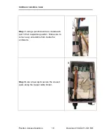
Page 17: ...e top of the enclosure Once done make sure to tighten the sealing nut to maintain IP67 protection Step 5 select the pairs to connect and bend the remaining unused pairs along the copper cable binder section inside the enclosure This is useful should you need to connect more pairs or use different pairs Step 6 position the pairs 1 per port when operating in SISO mode and 2 per port when in MIMO mod...

Page 18: ...ions 18 Document 180 0211 001 R01 Step 7 using a punch down tool install each pair in their respective position Make sure to remove any wire debris from inside the enclosure Step 8 use a tie wrap to secure the unused pairs along the copper cable binder ...

Page 19: ...AM 4 MX GAM 8 MX kit Step 9 The 12Vdc connector is located at the top right corner of the GAM enclosure Pull on the male power connector that ships pre installed in unit Step 10 using 18 AWG wire insert the power cable through the rightmost cable gland You can then connect the 12Vdc power pair to the male power connector and tighten with a small flat screwdriver ...

Page 20: ...ther end of the 12Vdc 4A adapter to the local 110 220VAC power source The next step is the insertion of the SFP or SFP module that provides the uplink connection Step 12 Insert the SFP or SFP module into the SFP cage at the top right section of the GAM enclosure Make sure to lock the SFP SFP module in place Note the SP cage can accommodate modules that draw up to 3W of power ...

Page 21: ...e enough length to reach the SFP cage while routing the fiber cable above the 2 x RJ 45 ports at the top right of the GAM enclosure Step 14 insert the fiber connectors into the SFP SFP module Note while an LC patch cable is shown here you can also use an SC patch cable or a copper CAT 5 6e when using a copper SFP Step 15 make sure you carefully route the fiber patch above and around the RJ 45 conn...

Page 22: ... 22 Document 180 0211 001 R01 You are now ready to install the ground wire into the ground lug at the bottom right edge of the GAM enclosure Step 16 insert the 6 AWG ground wire into the ground lug Step 17 use a 4 mm Allen hex key to secure the ground wire ...

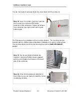
Page 23: ... bottom right The final step is the installation of the mounting bracket The mounting bracket included with the GAM enclosure facilitates installation on a pole or a flat surface You can also strand mount the device using the optional GAM STRAND KIT adapter Step 19 the top and bottom brackets are identical Using the Phillips screws supplied with the unit to fasten the bracket on the back side of t...

Page 24: ...GAM Quick Installation Guide Positron Access Solutions 24 Document 180 0211 001 R01 Chapter 3 ______________________________________ WEB Management ...

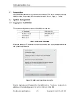
Page 25: ... 1 Logging into the WEB GUI The default configuration values of the GAM devices are IP Address 192 168 10 1 Subnet Mask 255 255 255 0 Username admin Password Table 4 GAM default credentials Enter the system s IP Address into the Web browser and a login screen similar to the following will appear Figure 10 GAM Login Page Browser specific Enter a Username and Password for the GAM device The default ...

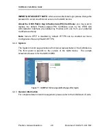
Page 26: ...ministration Interface pre installed by Positron with one from your preferred Certificate Authority Note Secure HTTP is disabled by default HTTPS can be enabled via menu Configuration Security Switch HTTPS 3 2 2 System The System monitor page provides a front panel representation of the GAM device The front panel is specific to the version of the GAM device The sample screenshot below is for the G...

Page 27: ...GAM Quick Installation Guide Positron Access Solutions 27 Document 180 0211 001 R01 Chapter 4 ______________________________________ Technical Specifications ...

Page 28: ...c Compatibility EN 55032 FCC Part 15 Class A Other mark CE Operating Temperature 40ºC to 65ºC Storage Temperature 40ºC to 70ºC Operating Humidity Up to 95 relative non condensing 10 Gbps Network Network Interface NNI 1 x SFP port SFP offer versatile support for Active Ethernet and for GEPON 10GEPON NG PON2 and XGS PON via external ONU ONT devices Also compatible with 3rd party PON SFP ONT modules ...

Page 29: ...k FEXT mitigation via VectorBoost vectoring Reliability and Resiliency State of the art LDPC Forward Error Correction FEC Layer 2 Switching Spanning Tree Protocol STP Standard Spanning Tree 802 1d Rapid Spanning Tree RSTP 802 1w Multiple Spanning Tree MSTP 802 1s MAC Table Up to 32K MAC addresses Trunking Link Aggregation Control Protocol LACP IEEE 802 3ad for any SFP or G hn ports VLAN Supports u...

Page 30: ...ides L2 isolation between clients in the same VLAN supports multiple uplinks Port Security Locks MAC Addresses to ports and limits the number of learned MAC addresses Storm Control Prevents traffic on a LAN from being disrupted by a broadcast multicast or unicast storm on a port ACLs Supports up to 256 entries Drop or rate limitation based on source and destination MAC VLAN ID or IP address protoc...

Page 31: ... firmware partition provide independent primary and secondary OS files for backup while upgrading Each firmware image has its corresponding firmware partition SNMP SNMP version1 2c and 3 with support for traps and SNMP version 3 user based security model USM Remote Monitoring RMON Embedded RMON software agent supports RMON groups 1 2 3 9 history statistics alarms and events for enhanced traffic ma...

Page 32: ...GAM Quick Installation Guide Positron Access Solutions 32 Document 180 0211 001 R01 Chapter 4 ______________________________________ Safety and Warnings ...

Page 33: ... Only qualified personnel should service this system All wiring external to the product should follow the local wiring codes Use of this product in a manner other than defined in this installation guide may cause damage to equipment or injury to personnel If a problem has been isolated to this unit do not attempt to repair The unit s components are not user serviceable and therefore must not be re...

Page 34: ... isolation from the exposed OSP cabling The addition of Primary Protectors is not sufficient protection to connect these interfaces metallically to OSP wiring Connection to these ports should be for temporary use during installation or maintenance THIS PRODUCT IS SUITABLE FOR MOUNTING ON OR ABOVE CONCRETE OR OTHER NON CONDUCTIVE SURFACE ONLY ...

Page 35: ...GAM Quick Installation Guide Positron Access Solutions 35 Document 180 0211 001 R01 Chapter 5 ______________________________________ Warranty and Customer Service ...

Page 36: ...ty information can be found in your Positron Access customer web portal http www positronaccess com Portal php Positron Access Solutions Sales Pricing Availability and Technical Support US and Canada 1 888 577 5254 International 1 514 345 2220 customerservice positronaccess com Repair and Return Address Contact Customer Service prior to returning equipment to Positron Telephone US and Canada 1 888...

Reviews: