

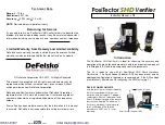

1. Remove the PosiTector
SHD Verifier
and Smart Sensor Indicator from the case.
Make sure to place the PosiTector
SHD
Verifier
on a stable flat surface.
2. Connect the Load Cell Cable to
the Smart Sensor Indicator
The PosiTector
SHD Verifier
includes Certificates of Calibration for the SSI
and load cell. For information on returning your PosiTector
SHD Verifier
for
recertification, contact DeFelsko
or your local dealer.
The PosiTector
SHD Verifier,
with valid Certificates of Calibration, can be
used to check the accuracy of PosiTector
SHD Shore Hardness
Durometers
. A sample Certificate of Accuracy is included.
The SSI device comes pre-configured for verification of PosiTector
SHD
Shore Hardness Durometers
. No additional configuration is required or
recommended.
If the SSI is mistakenly altered, configuration can be restored by following
the steps outlined in our
Reconfiguration Guide
. Contact DeFelsko for more
information.
2
3
PosiTector SHD Verifier Set-up
PosiTector SHD Verifier Set-up
Reconfiguring the SSI Device
Reconfiguring the SSI Device
Certification
Certification
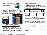
3. Select a
SHD A
(aluminum) or
SHD D
(brass) target and insert it into
the load cell as shown.
Note:
Inspect the targets before installing. To
prevent damage to the PosiTector
SHD D
probe tip, the
SHD D
(brass)
target is designed to be dented during testing and will periodically need to
be replaced. The
SHD A
(aluminum) target will not be dented during testing
and should be replaced if there is any damage to the top surface.
4.1 Perform a Gage
Reset
on the PosiTector
SHD
4.2 Select
Continuous Reading Mode
from the Setup menu on the
PosiTector
SHD
.
4.3 Turn the Micrometer Adjustment so that it is set between 1 and 2.
4.4 Place the PosiTector
SHD
probe into Probe Holder. Ensure that the
probe tip doesn’t touch the target.
For detailed instructions see the
PosiTector
SHD
Calibration Procedure
at dl.defelsko.com/pdf/manuals/PosiTectorSHD-Verifier-v1.0.pdf
Shore A
10
20
30
40
50
60
70
80
90
SHD Verifier
Displays (lbs)
0.292 0.461 0.629 0.798 0.967 1.135 1.304 1.472 1.641
Shore D
10
20
30
40
50
60
70
80
90
SHD Verifier
Displays (lbs)
0.999 1.999 2.998 3.997 4.996 5.996 6.995 7.994 8.994
4.5 Power on the Smart Sensor Indicator
4.6 Turn the Micrometer Adjustment to lower the probe onto the target until
the desired load is displayed on the
SHD Verifier
corresponding to the
Shore A
or
Shore D
verification points illustrated below.
4.7 Verify that the PosiTector
SHD
is reading 1 Shore value of
the corresponding load.
Repeat steps 4.6 – 4.7 for each verification point.
Quick Calibration Procedure
Quick Calibration Procedure
SHD
Target
Probe
Holder
Target
Micrometer
Adjustment
www.
.com
1.800.561.8187


