


10
5.
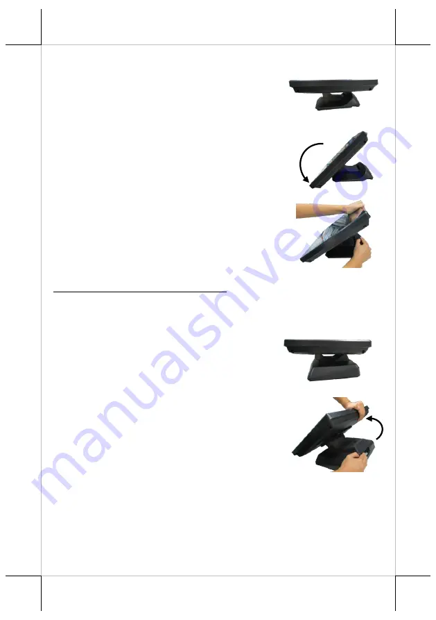
Position the terminal in
Low Profile mode
.
5.1
Follow Step 4 to set up the termimal in Flat
Folded mode.
5.2
Tilt the screen all the way down
5.3
To tilt screen up or down to your desired
angle, please be advised to keep the base
steady with one hand to do so. Do NOT
press on the LCD panel while setting up the
tilt angle.
XT-3815/3915/3915IR with Gen 8E Base
Please refer to the following instructions on how to switch among different
positioning modes to find an ideal viewing angle for XT-3815/3915/3915IR
with Gen 8E base.
1.
Unpack XT-3815/3915/3915IR, which is
supposed to be set in flat folded mode, out
of the package box and then lay your POS
system on a flat surface.
2.
While steadying the terminal with your
hand holding onto the base, tilt the screen
down.


