background image


Connecting Power Adapter and I/O Cables 

To have the terminal ready for operation, please connect the connector of 
power adapter and all of the connectors of required I/O cables respectively to 
the 12VDC-IN power jack and appropriate I/O ports. Please make sure that 
each of the cables is fully connected to the correct port. Damages due to 
incorrect connection or orientation are not covered by product warranty! 

Some cable connectors like the connectors of LAN or cash drawer (CR) cables 
have to be gently inserted until a click is heard. It is recommended that the I/O 
ports, such as COM port, parallel port, and VGA port, should be screwed after 
the I/O cable connectors are completely connected. And please make sure that 
each connector has to be connected to the right peripheral device in the right 
way.  

CAUTION: On doing insertion or extraction of a cable connector, please 
always hold the connector head itself instead of pulling the cable wire. 
Doing this could damage the cables and ports, which is considered as an 
artificial damage and is not covered by the warranty. The means of power 
cord should be connected to a socket-outlet with earthing connection. 

ATTENTION: Lors de l'insertion ou de l'extraction d'un connecteur de 
câble, veuillez toujours tenir la tête du connecteur elle-même au lieu de 
tirer le fil du câble. Cela pourrait endommager les câbles, ce qui est 
considéré comme un dommage artificiel et n'est pas couvert par la 
garantie. Le cordon d'alimentation doit être connecté à une prise de 
courant avec mise à la terre. 


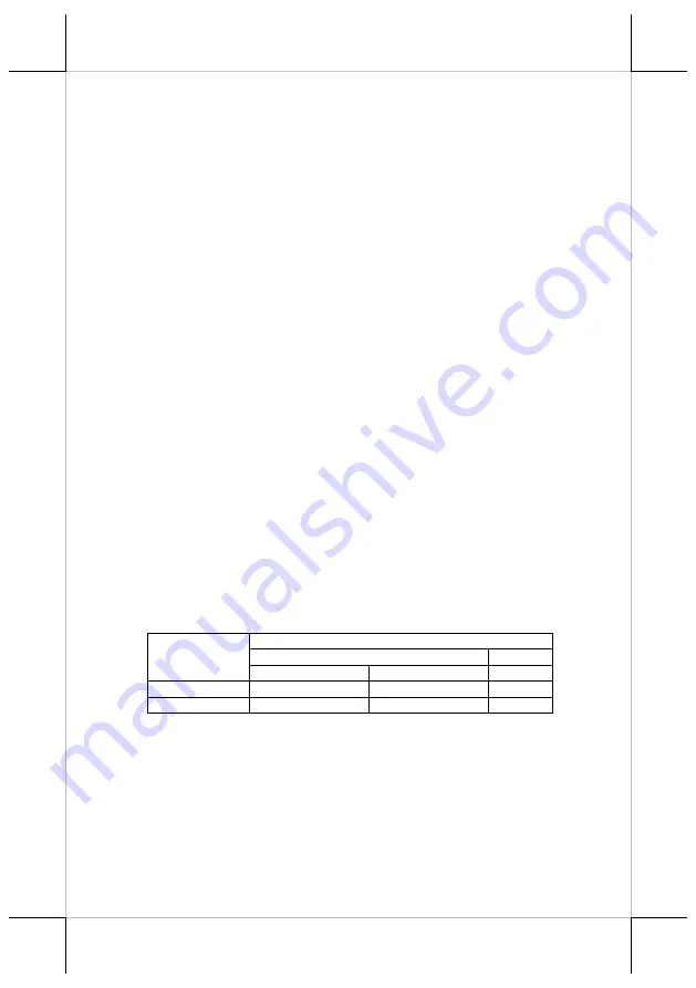
Note: The COM ports of TX-5600/5600E/5700/5700E do not supply power by 

default. To make the COM ports supply power, you can set up the 
COM ports through the dedicated settings listed in the table below.  


The VGA port of TX-5600/5600E/5700/5700E can 12VDC 
power through system BIOS setting for Posiflex LCD monitor. 
Nevertheless, except Posiflex VGA monitor, do not connect any other 
monitor to this port with VGA power enabled. 


TX-5600/5600E/5700/5700E 

COM1/2/3 

VGA 

5VDC 

12VDC 

12VDC 

BIOS Setting 


Jumper Setting 


Summary of Contents for TX-5600

Page 1: ...5700 5700E POS box x1 12VDC 84W power adaptor TX 5600 5700 or 12VDC 150W power adaptor TX 5600E 5700E x1 Power cord x1 Wall mount bracket optional x1 User manual x1 14550903010 Ver A0 http www posifl...

Page 2: ...ce that may cause undesired operation CE CLASS A WARNING This equipment is compliant with Class A of CISPR 32 In a residential environment this equipment may cause radio interference AVERTISSEMENT CE...

Page 3: ...explosion or the leakage of flammable liquid or gas A battery subjected to extremely low air pressure that may result in an explosion or the leakage of flammable liquid or gas BATTERIE ATTENTION NOTES...

Page 4: ...of TX 5600E 5700E Top View of TX 5600 5700 5600E 5700E Power Button Powered USB Port Storage Status LED Indicator Power Status LED Indicator Heat Dissipation Fins Power Button USB 2 0 Port Power Stat...

Page 5: ...ar I O Ports TX 5600 5700 5600E 5700E 1 Mic in line out combo jack 2 USB 3 0 port 3 RJ45 LAN port 4 RJ11 cash drawer CR port 5 DVI port 6 HDMI port 7 VGA port 8 COM port 9 12VDC IN power jack Rubber P...

Page 6: ...pulling the cable wire Doing this could damage the cables and ports which is considered as an artificial damage and is not covered by the warranty The means of power cord should be connected to a soc...

Page 7: ...system is provided with a second storage bracket for you to install an optional second storage To avoid users from damaging the main board of the system it is highly recommended that the optional seco...

Page 8: ...ket installation guide Powering ON OFF the POS Box Power ON TX 5600 5600E 5700 5700E Press down the power button to power on the TX 5600 5600E 5700 5700E Power OFF TX 5600 5600E 5700 5700E In most cas...

Page 9: ...tware restoration after the OS is recovered If you plan to recover your operating system we do NOT encourage you to recover any operating system Please contact your service center for operating system...

Page 10: ...l speaker Storage SATAIII x 2 M 2 2280 Extension Slot M 2 2230 Power Switch Soft switch Mechanical Installation Desktop or wall mount VESA mount 75 x 75 Wall Mount Bracket Optional WB 4200 LED Indicat...

Page 11: ...11 MEMO...

Page 12: ...12 MEMO...

Reviews: