background image


Part 12

for within 10 seconds. 

There must always be at least 10 seconds waiting before switching on 

again once the system is powered off successfully. 

Automatic Power On Control

The system may also turn on according to some preset conditions 

such as Modem Ring Up or Alarm Clock Wake Up or LAN Wake Up. 

To utilize Modem Ring Up or Alarm Clock Wake Up function, the 

user should enter the BIOS setup by pressing “Del” key at system boot up, 
choose in “Power Management Setup” and make the “Power On by Ring” 
enabled for Modem Ring Up or enable the “Resume by Alarm” for Alarm 
Clock Wake Up. Save the configuration and exit the BIOS setup program. The 
Preset Power On Control will then be ready. For LAN wakeup, the item “PCI 
Express PM Function” must be enabled in “Power Management Setup” and an 
operating caller system connected through LAN to the system is required. It 
also requires a qualified networking technician to check the LAN chip ID of 
the system for the caller system to wake up. 

When the KS-6812 system is turned off after a successful boot up 

with external power continuously supplied, the preset automatic power on 
functions will keep monitoring for the preset conditions and turn on the system 
when the preset conditions are met. 

Please note that if the KS-6812 system is improperly turned off before 

a complete boot up procedure, the above preset power on control functions will 
be disabled until next turning off after a complete boot up. 

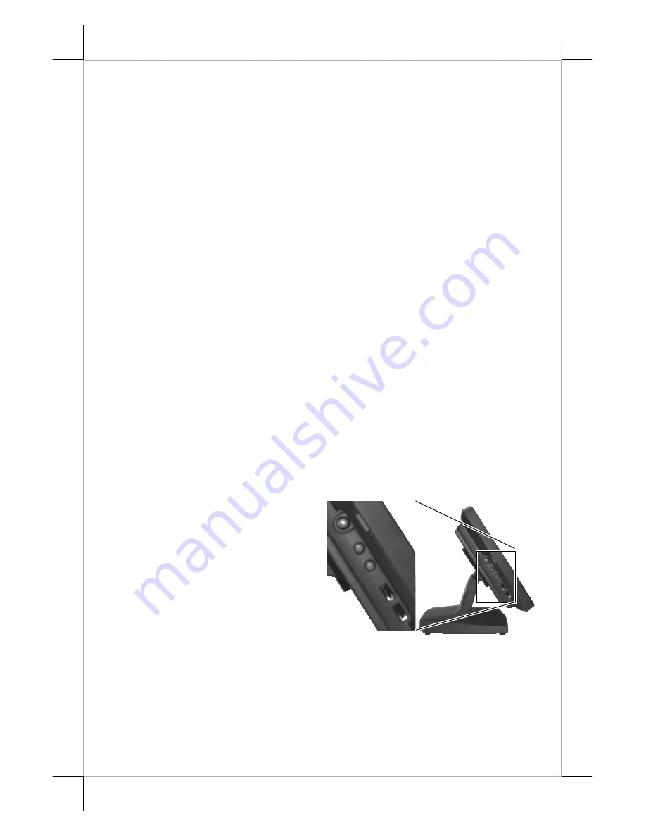
BRIGHTNESS CONTROL

At left side of the main unit 

below the power switch, there are 
brightness adjust push button 
switches and two USB connectors. 
Each single press on the + or – button 
changes the LCD panel display 
brightness by a small amount. When 
you press and hold the button the 
change will keep on until release or 
extreme condition matched. 

USB PORTS

There are in total 6 USB ports for external connection: 2 at left side 

below power switch and LCD brightness adjust buttons; 4 in I/O area. All of 
them comply to USB 2.0 standard. 

Summary of Contents for KS-6812

Page 1: ...a or profits resulting from the furnishing performance or use of this material This information is provided as is and Posiflex Technologies Inc expressly disclaims any warranties expressed implied or statutory including without limitation implied warranties of merchantability or fitness for particular purpose good title and against infringement The information in this manual contains only essentia...

Page 2: ...d batteries and always replace only with battery of same type DAILY MAINTENANCE GUIDE For regular cleaning of the KS systems please use only soft haired brush or dry soft cloth You may use moist soft cloth to remove stains when necessary Apply only proper amount of mild neutral detergent for obstinate stains Please note that never use Acryl dissolving solvent or Polycarbonate dissolving solvent Yo...

Page 3: ... PRODUCT PICTURES Front View Rear View Side Views Bottom View Inside Base PARTS IDENTIFICATION 1 Main unit 2 Touch panel LCD panel 3 Power indicator 4 Base stand 4 6 1 5 3 7 8 2 1 9 18 16 20 17 19 7 12 15 13 13 5 11 10 14 ...

Page 4: ...nit d An advanced mini slim base design that supports storage room for optional 2 5 SATA HDD e Support WinXP Pro WEPOS and Linux OS f High quality 12 TFT active matrix LCD panel XGA g Vertical type LCD panel with easy tilt angle adjustment from 20 to 90 h LCD brightness adjust buttons at side of main unit i Durable resistive type touch panel that endures 35 million touches min at same spot j Vario...

Page 5: ...nit is unlikely to be activated in normal operation q Preconditioned power up function by alarm clock or COM port MODEM ring or LAN r Supports power saving by suspension mode Option Items Note The underlined items in the following list means that option must be set prior to shipment from the factory The rest items can be set by the dealers a DDR2 SODIMM memory expansion up to 2GB max b CF card rea...

Page 6: ...TING LCD PANEL The tilting mechanism in KS 6812 series utilizes hinges and there is no particular skill to turn the LCD panel to most suitable angle for either viewing or convenience in cable connection disconnection DISCONNECTING ALL CABLES With the LCD panel turned to most backward position the main I O connector area will be easily accessible at bottom side of the main unit Please first note or...

Page 7: ...e trunk as triangle marked to come out of the front side of trunk Connect all the cable ends to main unit Should there is the option SATA HDD in base installed please double check that the HDD cables must be still secured BASE MOUNT UPGRADE KIT OPTION Pole Display For the KS 6812 series with mini slim base the LCD customer display PD 309 U or the VFD PD 2605 U can be attached to either rear corner...

Page 8: ...plied to the connector as triangle marked in the picture Route the other end of the conversion cable through the oval opening in base trunk and have the usual cable for parallel device connected SIDE MOUNT UPGRADE KIT OPTION Remove the 2 screws circled in the left picture to remove the cover for side mount upgrade kit Take out the cable inside this cover and connect it to the white connector insid...

Page 9: ...for the two 8 pole plugs are different Use the shorter one for the original cash drawer CR1 and use the longer one for the extended cash drawer CR2 that will be distinguished by the software command CONNECTING CABLES To have the re assembled main unit with stand assembly ready for operation please connect all required cables to the appropriate connectors Please make sure that each connector is con...

Page 10: ... software restoration after OS recovered A Posiflex supplied USB interface COMBO drive will be required for such action Other brand COMBO drive may require its specific driver different from what supported in the recovery DVD Please use the recovery DVD in rescue operation only Using it otherwise may wipe out whatever stored in the HDD All upgrade devices drivers needed for manual installation in ...

Page 11: ...g arrangements must conform to local safety regulations Please never do any connection disconnection when system is still powered on Please always keep the external power adaptor in a free air circulation POWER ON OFF CONTROL Power Indicator There is a power indicator LED at center of lower rim of LCD panel This LED lights up orange when external power is ready and turns to blue when system power ...

Page 12: ...tworking technician to check the LAN chip ID of the system for the caller system to wake up When the KS 6812 system is turned off after a successful boot up with external power continuously supplied the preset automatic power on functions will keep monitoring for the preset conditions and turn on the system when the preset conditions are met Please note that if the KS 6812 system is improperly tur...

Page 13: ...in 1 LM 3112 SERIAL PORTS COM1 2 3 In KS 6812 system there are 3 serial ports available All can supply a 5 V DC through pin 9 after proper jumper setting change COM1 2 ports are standard RS232 serial ports as status at delivery COM3 is also set to standard RS232 serial port as status at delivery if the option conversion cable is applied PARALLEL PORT In KS 6812 system the parallel port can be avai...

Page 14: ...CH PANEL All paragraphs below are applicable for models with touch panel only The user of those models without touch panel can ignore them and consider this user s manual ends here Mouse Emulation The touch panel in KS system uses USB interface When the touch driver is properly installed this touch panel works exactly like a standard mouse of USB interface However if the system is running under sa...

Page 15: ...USB Touch Manager and a right click sticky button tool in the program group Posiflex USB Touch Tools is installed in the preloaded Windows system with a USB interface touch panel controller This program can also be obtained by download from the POSIFLEX web site ...

Page 16: ...KS 6812 series if no pole display is attached Refer to the picture at left Use the 2 attached screws to fix the metal base of the LM to the bottom plate of mini slim base at the circled positions Connect the VGA cable to go through the cable exit to the VGA port after the 12V DC support in KS 6812 is enabled ...

Page 17: ...Part 17 ...

Page 18: ...Part 18 ...

Page 19: ...Part 19 ...

Page 20: ...Part 20 ᙆѓԴ 這是甲類的資訊產品 在居住的環 境中使用時 可能會造成射頻干 擾 在這種情況下 使用者會被要 求採取某些適當的對策 T31454 ᙆѓ 本電池如果更換不正確會有爆炸的危險 請依製造商說明書處理用過之電池 ...

Reviews: