background image


2 - 4 

5. 

Power on 

When all the above cable connections are made correctly, 

you may connect your power adaptor to the wall outlet. Make 
sure that the type of power cord and the voltage requirement of 
the power adaptor meet the local power conditions. Now the 
printer is ready for power on. 

6. 

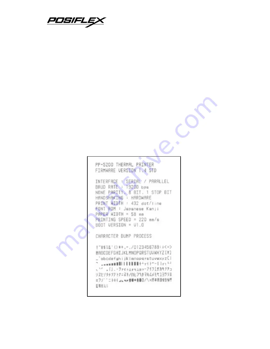
Self test 

Press and hold down the feed button while turning the 

power switch on. The printer will then perform a self  test. A 
sample slip of self test result is printed below. Please note that 
both serial and parallel interfaces are indicated. That means the 
printer is working on an auto-sensing and auto-select algorithm. 


Summary of Contents for Aura PP-5000

Page 1: ...5200 Thermal Printer User s Guide IMPORTANT Please read carefully before using this printer Before opening the Top Hood make sure there is no paper jam or cutter jam trouble Read page 3 4 3 5 and Warranty Limit in the user s Manual ...

Page 2: ...ly when the machine is opened by any person other than the authorized technicians The user should consult his her dealer for the problem happened Warranty voids if the user does not follow the instructions in application of this merchandise The manufacturer is by no means responsible for any damage or hazard caused by improper application About This Manual This manual is aimed to assist the user t...

Page 3: ...to replace paper 2 2 CONNECTING CABLES 2 2 Serial connection 2 2 Parallel connection 2 2 Peripheral connection 2 3 Power connection 2 3 Power on 2 4 Self test 2 4 SPECIAL ADJUSTMENTS 2 5 Paper near end sensor 2 5 Paper roll placement 2 5 Paper cutting 2 6 Wall mount application 2 6 MAINTENANCE GUIDES 3 1 MAINTENANCE GUIDE LINES 3 1 GENERAL CLEANING 3 1 PRINT HEAD CLEANING 3 1 TROUBLE SHOOTING 3 2 ...

Page 4: ...uto cutter problems 3 4 Advanced analysis tool 3 6 SPECIFICATIONS 4 1 PRINTER 4 1 PAPER 4 1 POWER ADAPTOR 4 2 TECHNICAL INFORMATION 5 1 INTERFACES 5 1 Peripheral interface 5 1 Serial interface 5 2 SETUP WINDOW 5 2 ADVANCED SETTINGS 5 4 USEFUL TIPS 6 1 ...

Page 5: ... incl model PP 5200 printer uses thermal sensitive paper in form of a roll at a width of 58 mm standard or 38 mm option for PP 5000 only The Aura PP 5000 series printer serves the stand alone desk top application as well as the application within a Posiflex integrated POS system equally perfect The Aura PP 5000 series support two types of interface input through different sub codes to the model nu...

Page 6: ... is any discrepancy or problem contact your dealer immediately Be sure to save the packing materials in case the printer needs to be shipped at some point in the future The printer itself Thermal paper roll 58 mm wide ƒ One of the interface cables a Serial cable with 9 pin D sub Female to 8 pin RJ 45 jack for Aura PP 5000 S or Aura PP 5200 S b Parallel cable with 25 pin D sub Male to 25 pin D sub ...

Page 7: ...POS system This User s Manual D OPTIONS 38 mm paper roll adaptor for PP 5000 only Kitchen bell KL 200 Language to add to standard model Japanese Kanji Korean Traditional Chinese or Simplified Chinese etc Wall mount kit E MAIN PARTS ON THE EXTERIOR Case Power LED Error LED Paper Out LED FEED Switch Top Hood Hood Release Button Power Switch Cutter Cover ...

Page 8: ...CATORS Power LED green Error LED red Paper Out LED red Parallel Connector Serial Connector Power Connector Peripheral Connector Rear View Screws Window Plate Screw Setup Window Bottom View Power Switch Front View ...

Page 9: ... release the top hood 2 Raise the released hood wide open manually 3 Drop the thermal paper roll inside the printer in the orientation as shown in the picture 4 Close the hood back leaving the tail of the paper roll coming out of the opening between the hood and the top cover Tear off excessive paper ...

Page 10: ...eft in the picture above Apply the RJ45 plug of RS232 cable to this port for serial application Please note that when serial connection is used there must be no cable connection at the parallel port on the printer The default protocol used in serial connection is 19200 bps none parity 8 data bits 1 stop bit Set in setup window the switch positions both 1 and 2 to OFF leaving the rest unchanged as ...

Page 11: ...h drawers of above models When the printer is used as a kitchen printer please use this port for kitchen bell connection instead 4 Power connection The power connector is a 3 pin jack at the rightmost position in the connector area Either a Posiflex supplied power adaptor or a printer power cable from a Posiflex POS system can be connected to this connector to supply power for this printer During ...

Page 12: ...wer adaptor meet the local power conditions Now the printer is ready for power on 6 Self test Press and hold down the feed button while turning the power switch on The printer will then perform a self test A sample slip of self test result is printed below Please note that both serial and parallel interfaces are indicated That means the printer is working on an auto sensing and auto select algorit...

Page 13: ...r bobbin size adjustment and a sensor block in the wall Turn the thumb wheel to adjust the proper position of sensor block For desktop application the sensor block should be above the bobbin seating on the 2 support rollers on bottom of paper compartment when paper near end For wall mount application the sensor block should be under the bobbin supported through a shaft held on paper compartment wa...

Page 14: ...uses direct cut instead of protective cut to have something like a logo printed on top of each slip it is also highly suggested to print the logo and necessary paper feeding to make 12 mm paper advance right after each cut to prevent curling up and jamming of paper front edge inside the paper exit slot 4 Wall mount application In wall mount application the option kit will include screws plastic co...

Page 15: ...ir brush or compressed air to clear away any dust or paper scraps accumulation inside the printer Check also the area of the auto cutter regularly C PRINT HEAD CLEANING The print head is located underneath the roll paper passage at the exit as in the picture below You can clean the thermal elements of the print head and paper end sensor gently using a cotton swab moistened with isopropyl alcohol s...

Page 16: ...aper roll is not installed or is at or near the end Install a new paper roll If the Paper Out LED is OFF please check if the top hood is properly closed There are 2 internal check points inside the printer to assure the locking of the hood for a decent printing Therefore any dislocation of the hood may cause an error status and inhibition to printing Press down the hood at middle of the opening wh...

Page 17: ...ealer or a qualified service person Poor printing quality Contaminants like paper scraps and dusts on the thermal print head can lower the print quality drastically Clean the print head as described in previous section Printer trembles when printing Since PP 5000 PP 5200 prints at 120 or 220 mm sec that is extremely high speed the printer may tremble due to frequent engagement of the brake and acc...

Page 18: ...Please also clear away any contaminants accumulated in the cutter track above the thermal elements 4 Auto Cutter Problems In case any foreign materials like a staple or paper clip or excessive paper scraps fall into the auto cutter mechanism the auto cutter may lock up and so does the print hood In such case please push the cutter cover down and forward as in the right picture to access the adjust...

Page 19: ... blade back to its home position Apply some mechanical assistance if necessary When the cutter blade returns to its standard position a through hole in the plastic gear will show up in the window as illustrated below Then close the cutter cover back to position when finish The lock up of the print hood can then be released after this problem solved Push down to test release Top Hood Use Phillips s...

Page 20: ...r to view exactly what data is received by the printer This can be useful in finding software problems To start the dump mode Turn off printer Open print hood Hold down FEED button while turning printer on Close the hood To stop the dump mode Press the FEED button to print out the last line Turn off the printer During dump mode All commands except DLE EOT and DLE ENQ are disabled ...

Page 21: ...cutter type Guillotine type Auto cutter capability Partial cut 1 point at center left Manual cutter Saw tooth blade Dot Pitch 0 125 x 0 125 mm Input power type DC Input voltage 24 V 5 Dimension mm 120 W x 203 D x 124 H Weight 1 15 Kg net B PAPER Paper type Thermal roll paper Paper roll formation External side is heat sensitive side 58 0 1 mm Paper width 38 0 1 mm for PP 5000 with paper adaptor opt...

Page 22: ...UIREMENT INPUT VOLTAGE 100 V AC 250 V AC INPUT FREQUENCY 50 60 HZ INPUT CURRENT 1 5 A MAX 115 V AC OUTPUT VOLTAGE 24 V DC OUTPUT POWER 60 W STATIC LOAD 0 A 2 5 A OUTPUT REGULATION 5 MTBF 30 000 HRS EMI STANDARDS VDE B FCC B VCCI B ...

Page 23: ... using an optional split cable 20867023800 CCBLA 238 Aura series controls two cash drawers through this connector Please connect the CR1 plug to the cash drawer CRA to be opened by command Esc p 1 n1 n2 and the CR2 plug to the cash drawer CRB to be opened by command Esc p 0 n1 n2 PIN Definition Description 1 FG Frame ground 2 CRB Drawer kick for cash drawer controlled by software command Esc p 0 n...

Page 24: ...it The pins between the 2 plugs are connected pin to pin That is pin 1 of one plug is connected to pin 1 of the other plug and pin 2 connected to pin 2 etc The converter could be market available The connections between the two ends are RXTXDTRGND CTS DB9F RJ45 jack pin 1 pin 1 pin 2 pin 2 pin 3 pin 3 pin 4 pin 4 pin 5 pin 5 pin 6 pin 6 pin 7 pin 7 pin 8 pin 8 pin 9 N C B SETUP WINDOW On bottom co...

Page 25: ...Effect of positions 1 2 on baud rate is defined as in table below with parity check set according to position 3 number of data bits always set to 8 and stop bit set to 1 When the parallel interface is used please set both positions to ON SW Pos 1 ON OFF ON OFF SW Pos 2 ON ON OFF OFF Baud rate or Interface 38400 bps Parallel 4800 bps 9600 bps 19200 bps Switch position 3 defines the parity check reg...

Page 26: ... in replace till paper is replaced For switch position 6 when it is set to OFF there will be a 20 mm paper feed before cutting when software does not define this point and there will be further 10 mm paper after cutting to prevent paper jam Before setting this switch to ON please make sure that your software will take care of enough paper feed for the paper jam prevention issue For switch position...

Page 27: ...ct sunlight or near a heater Ideal room temperature is from 0ºC to 50ºC Ideal humidity is from 10 to 90 RH no condensation Do not set any liquid or drinks such as coffee on the printer case Do not touch any metal part to avoid possible electrostatic damage Do not touch the areas around the print head and motor during or right after printing It can be very hot Do not allow the cut receipt to slide ...

Page 28: ...polyvinyl paste or CMC paste when gluing thermal paper If thermal paper touches anything containing phthalic acid ester plasticizer for a long time the image formation ability may be reduced or the printed image may fade Use of volatile organic solvents such as alcohol ester and ketone or some adhesive tapes on thermal paper can cause discoloration Thermal paper must not be stored with the printed...

Reviews: