WEBS-21A0
Fan-less Embedded System
User's Manual
Version 1.0
Copyright © Portwell, Inc., 2017. All rights reserved.
All other brand names are registered trademarks of their respective owners.
Page 1: ...WEBS 21A0 Fan less Embedded System User s Manual Version 1 0 Copyright Portwell Inc 2017 All rights reserved All other brand names are registered trademarks of their respective owners ...
Page 2: ...ting 2 5 2 6 Getting Started 2 5 2 7 I O Interfaces 2 6 2 7 1 Front View Standard 2 6 2 7 2 Front View Optional Kit Additional 2x USB 3 0 2 6 2 7 3 Rear View 2 6 Chapter 3 BIOS Setup Information 3 1 3 1 Entering Setup Launch System Setup 3 1 3 2 Main 3 2 3 3 Configuration 3 3 3 4 Security 3 22 3 5 Boot 3 23 3 6 Exit 3 26 Chapter 4 Important Instructions 4 1 4 1 Note on the Warranty 4 1 4 2 Exclusi...
Page 3: ...e the system Chapter 3 BIOS Setup Information Specify the meaning of each setup parameters how to get advanced BIOS performance and update new BIOS In addition POST checkpoint list will give users some guidelines of trouble shooting Chapter 4 Important Instructions Indicate some instructions which must be carefully followed when the fan less embedded system is used Chapter 5 Frequent Asked Questio...
Page 4: ... 232 422 485 selected by BIOS one audio combo jack to support Line out and Mic in and multiple storage with 2 5 HDD SSD mSATA device In addition the compact 150mm x 150mm x 63mm box WEBS 21A0 integrates a half size mini PCIe socket interface to support WIFI Bluetooth 3G functions etc making it an ideal solution as an IoT gateway The rugged fan less design makes the WEBS 21A0 durable in harsh envir...
Page 5: ...mmable by embedded controller H W Status Monitor Temperature CPU System Voltage CPU Vcore 12V 5V 3 3V 1 35V Expansion 1x Half size Mini PCIe socket External I O Series Ports 1x RS 232 422 485 COM Port selected by BIOS Display 2x mini DP USB 1x USB 3 0 2x USB 2 0 Optional kit additional 2x USB 3 0 Audio Audio Combo Jack Lin out Mic in Realtek ALC892 LAN 2x Gigabit Ethernet Intel I218AT Other 1x Ant...
Page 6: ...User s Manual 1 3 1 4 Mechanical Dimension Front view of the WEBS 21A0 system standard Front view of the WEBS 21A0 system with optional kit addition 2x USB 3 0 Rear view of the WEBS 21A0 system Side view of the WEBS 21A0 system ...
Page 7: ...System Overview WEB 21A0 User s Manual 1 4 Top view of the WEBS 21A0 system ...
Page 8: ...ting please refer to user s manual of NANO 6050 2 1 HDD Installation It s easy to install and maintenance the 2 5 HDD SSD by just open the back cover The height must be less than 10mm Step 1 Loosen the 4 screws of the back cover Step 2 Take out the back cover Step 3 Loosen the 4pcs screws and take out the HDD bracket Step 4 Install 2 5 HDD SSD on the bracket with screws M3x10L 4 Step 5 Attach HDD ...
Page 9: ...cover Step 1 Loosen the 4 screws of the back cover Step 2 Take out the back cover Step 3 Assemble the Half size Mini PCIe card and make sure it has been screwed Step 4 Install the SMA cable onto main connector of module M2 5x4L Step 4 Put the Antenna cable through the antenna hole Step 5 Install the Antenna Step 6 Position the back cover Step 7 Tighten the 4 screws of the back cover ...
Page 10: ...on It s easy to install and maintenance the 1x mSATA by just open the back cover Step 1 Loosen the 4 screws of the back cover Step 2 Take out the back cover Step 3 Assemble the mSATA card and make sure it has been screwed Step 4 Tighten the 4 screws of the back cover M2 5x6L ...
Page 11: ...Step 1 Loosen the 4 screws of the back cover Step 2 Take out the back cover Step 3 Take out the front side cover Step 4 Prepare the Din Rail mounting side cover Step 5 Assemble the new side cover with DIN Rail mounting device Step 6 Position the back cover Step 7 Tighten the 4 screws of the back cover Step 8 Clip the DIN Rail onto the device and make sure it has been locked tightly ...
Page 12: ...eed press the power button SW1 AT Mode or ATX Mode Selection 2 6 Getting Started It is easy to get the system started Step 1 Make sure the power supply 12V is connected properly Step 2 Press the power button to turn on the system SW1 Function 1 4 ON 2 3 ON ATX Mode default 1 4 ON 2 3 OFF ATX Mode 1 4 OFF 2 3 ON ATX Mode 1 4 OFF 2 3 OFF AT Mode ...
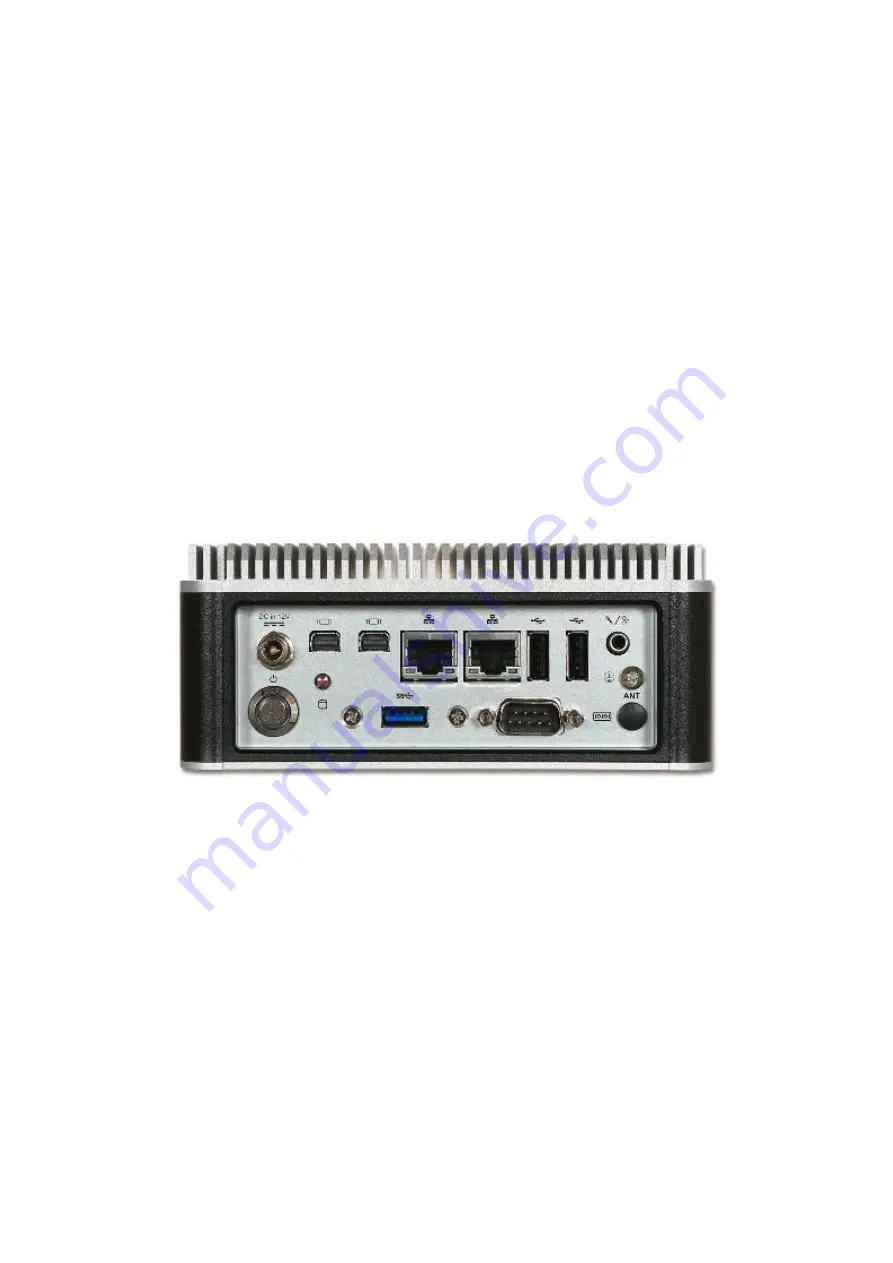
Page 13: ...allation WEB 21A0 User s Manual 2 6 2 7 I O Interfaces 2 7 1 Front View Standard 2 7 2 Front View Optional Kit Additional 2x USB 3 0 2 7 3 Rear View DC in 12V Using the provided DC source to connect to the system ...
Page 14: ...N ports by using Intel I218AT Ethernet Controller USB 2 0 Two USB 2 0 Universal Serial Bus ports USB 3 0 One USB 3 0 Universal Serial Bus port RS 232 422 485 Note RS 232 422 485 configuration is determined by BIOS setting Check BIOS setting for details PIN No Signal Description PIN No Signal Description 1 DCD 485D 422T 2 RXD 485D 422T 3 TXD 422R 4 DTR 422R 5 Ground 6 DSR 7 RTS 8 CTS 9 RI 10 N C Au...
Page 15: ...When the message below appears on the screen press ESC or DELETE key will enter BIOS setup screen Press ESC or DEL to enter SETUP If the message disappears before responding and still wish to enter Setup please restart the system by turning it OFF and On or pressing the RESET button It can be also restarted by pressing Ctrl Alt and Delete keys on keyboard simultaneously Press F1 to Run General Hel...
Page 16: ...Use this menu for basic system configurations such as time date etc Feature Description Options System Date The date format is Day Month Date Year Use or to configure system Date System Time The time format is Hour Minute Second Use or to configure system Time ...
Page 17: ...BIOS Setup Information WEB 21A0 User s Manual 3 3 3 3 Configuration Use this menu to set up the items of special enhanced features ...
Page 18: ...ctive Processor Cores Number of cores to enable in each processor package All 1 Limit CPUID Maximum Disabled for Windows XP Disabled Enabled Execute Disable Bit XD can prevent certain classes of malicious buffer overflow attacks when combined with a supporting OS Windows Server 2003 SP1 Windows XP SP2 SuSE Linux 9 2 RedHat Enterprise 3 Update 3 Disabled Enabled Intel Virtualization Technology When...
Page 19: ...ed Enabled C1 state auto demotion Processor will conditionally demote C3 C6 C7 requests to C1 based on uncore auto demote information Disabled Enabled C3 state auto demotion Processor will conditionally demote C6 C7 requests to C3 based on uncore auto demote information Disabled Enabled Package C state demotion Enable Package C state demotion Disabled Enabled C1 state auto un demotion Un demotion ...
Page 20: ...CH Disabled Enabled Above 4GB MMIO BIOS assignment Enabled Disabled above 4GB Memory MappedIO BIOS assignment Enabled Disabled Azalia Control Detection of the Azalia device Disabled Azalia will be unconditionally disabled Enabled Azalia will be unconditionally enabled Enabled Disabled Port 80h Redirection Control where the Port 80h cycles are sent LPC Bus PCIE Bus ...
Page 21: ...e Disable Intel Active Management Technology BIOS Extension Note iAMT H W is always enabled This option just controls the BIOS extension execution If enabled this requires additional firmware in the SPI device Disabled Enabled Un Configure ME OEMFlag Bit 15 Un Confugure ME without password Disabled Enabled Disable ME Set ME to Soft Temporary Disabled Disabled Enabled ...
Page 22: ...PXE Rom Launch Legacy PXE Rom Disable Not launch Rom Enable Force launch Rom Auto Auto detect LAN cable status to Enable Disable Rom initial Disable Enable Auto Intel LAN I210 Controller Enable or disable Intel LAN I210 Disabled Enabled Wake on LAN Enable or disable integrated LAN to wake the system The Wale On LAN cannot be disabled if ME is on at Sx state Enabled Disabled Launch Legacy PXE Rom L...
Page 23: ...M 384M 416M 448M 480M 512M 1024M 2016M DVMT Total Gfx Mem Select DVMT5 0 Total Graphic Memory size used by the Internal Graphic Device 128M 256M MAX Primary IGFX Boot Display Select the Video Device which will be activated during POST This has no effect if external graphics present Secondary boot display selection will appear based on your selection VBIOS Default Mini DP Port1 Mini DP Port2 LVDS A...
Page 24: ...Profile for current use 640x480 800x480 800x600 1024x768 1280x800 1280x1024 1366x768 1440x900 1920x1080 Color depth and data format Select color depth and data format VESA 24 bpp JEIDA 24 bpp VESA and JEIDA 18 bpp Channel Mode Select LVDS Channel Mode Single Channel Dual Channel Clock Mode Select clock output for LVDS Even Bus Odd Bus Both Buses ...
Page 25: ...r Management on both NB side and SB side of the DMI Link Disabled Enabled DMI Link Extended Synch Control The control of Extended Synch on SB side of the DMI Link Disabled Enabled PCIE Root Port Function Swapping Enable or Disable PCI Express PCI Express Root Port Function Swapping Disabled Enabled Subtractive Decode Enabled Enable or disable PCI Express Subtractive Decode Disabled Enabled Subtrac...
Page 26: ... Mini PCI Express Root Port Settings Feature Description Options PCI Express Root Port Control the PCI Express Root Port Disabled Enabled ASPM PCI Express Active State Power Management settings Disabled L0s L1 L0sL1 Auto PCIe Speed Select PCI Express port speed Auto Gen 1 Gen 2 ...
Page 27: ...Pluggable Disabled Enabled Mechanical Presence Switch Controls reporting if this port has a Mechanical Presence Switch Note Requires hardware support Disabled Enabled External SATA External SATA Support Disabled Enabled SATA Device Type Identify the SATA port is connected to Solid State Drive or Hard Disk Drive Hard Disk Drive Solid State Drive Port 1 Enable or Disable SATA Port Disabled Enabled H...
Page 28: ...eters Feature Description Options Legacy USB Support Enables Legacy USB support AUTO option disables legacy support if no USB devices are connected DISABLE option will keep USB devices available only for EFI applications Enabled Disabled Auto XHCI Legacy Support Enable Disable XHCI Controller Legacy support Enabled Disabled USB Mass Storage Driver Support Enable Disable USB Mass Storage Driver Sup...
Page 29: ...CI controller Smart Auto Auto Enabled Disabled BTCG Enabling disabling trunk clock gating Enabled Disabled USB Port 0 Enable Disable USB port Disabled Enabled USB Port 1 Enable Disable USB port Disabled Enabled USB Port 2 Enable Disable USB port Disabled Enabled USB Port 3 Enable Disable USB port Disabled Enabled USB Port 4 Enable Disable USB port Disabled Enabled USB Port 5 Enable Disable USB por...
Page 30: ...e the system will enter when the SUSPEND button is pressed Suspend Disabled S3 Suspend to RAM Wake on Ring Enable Disable GPIO Wake On Ring function Disabled Enabled RTC Wakeup Enabled Enable or disable System wake on alarm event Enabled system will wake on the hr min sec specified Disabled Turn off RTC Wakeup Disabled Enabled Wake up day Select 0 for daily system wake up 1 31 for which day of the...
Page 31: ... 1 Enable or Disable Serial Port COM Disabled Enabled UART Mode Set Current UART MODE RS232 RS485 RS485 RS422 RS232 RS485 HALF DUFLEX RS485 422 FULL DUFLEX Watch Dog Timer Enabled Enable Disable Watch Dog Timer Disabled Enabled Timer Unit Select Timer count unit of WDT Second Minute Timer value Set WDT Timer value seconds minutes 20 ...
Page 32: ...BIOS Setup Information WEB 21A0 User s Manual 3 18 H W Monitor Monitor hardware status ...
Page 33: ...Information WEB 21A0 User s Manual 3 19 Serial Port Console Redirection Serial Port Console Redirection Feature Description Options Console Redirection Enable Console Redirection Enable or Disable Disabled Enabled ...
Page 34: ...ode chars onto 1 or more bytes VT100 VT100 VT UTF8 ANSI Bits per second Selects serial port transmission speed The speed must be matched on the other side Long or noisy lines may require lower speeds 9600 19200 38400 57600 115200 Data Bits Data Bits 7 8 Parity A parity bit can be sent with the data bits to detect some transmission errors Even parity bit is 0 is the num of 1 s in the data bits is e...
Page 35: ...re RTS CTS VT UTF8 Combo Key Support Enable VT UTF8 Combination Key Support for ANSI VT100 terminals Disabled Enabled Recorder Mode With this mode enable only text will be sent This is to capture Terminal data Disabled Enabled Resolution 100x31 Enables or disables extended terminal resolution Disabled Enabled Legacy OS Redirection Resolution On Legacy OS the Number of Rows and Columns supported re...
Page 36: ...ntrol access to the system at boot time and or when entering the BIOS setup program Feature Description Options Password Check Mode Setup check password when enter setup screen Power on check password on every time system power on Setup Power On Administrator Password Set Administrator Password Create New Password ...
Page 37: ...0 can be disabled using BIOS services ALWAYS do not allow disabling GA20 this option is useful when any RT code is execute above 1MB Upon Request Always Option ROM Messages Set display mode for Option ROM Force BIOS Keep Current Storage Control the execution of UEFI and Legacy Storage OpROM Do not launch UEFI Legacy Full screen Logo Enables or disables Quiet Boot option and Full screen Logo Disabl...
Page 38: ...t Efi driver will still be installed with EFI OS Auto EFI Driver USB Support If Disabled all USB devices will NOT be available until after OS boot If partial Initial USB Mass Storage and specific USB port device will NOT be available before OS boot If Enabled al USB devices will be available in OS and post Disable Link Full Initial Partial Initial Network Stack Driver Support If Disabled Network S...
Page 39: ...ation WEB 21A0 User s Manual 3 25 Hard Drive BBS Priorities Set the order of the legacy devices in this group Feature Description Options Boot Option 1 Sets the system boot order Boot Option 2 Sets the system boot order ...
Page 40: ...anges Feature Description Options Save Changes and Reset Reset the system after saving the changes Discard Changes and Reset Reset system without saving any changes Restore Defaults Restore Load Default values for all the setup options Launch EFI Shell from filesystem device Attempts to Launch EFI Shell application Shell efi from one of the available filesystem devices Save configuration and reset...
Page 41: ...used by failure to abide by the hints in this manual and on the unit especially the safety instructions Portwell Inc shall not be required to respect the warranty even during the warranty period and shall be free from the statutory accident liability obligation 4 4 Declaration of Conformity EMC CE FCC Class A This equipment complies with Part 15 of the FCC Rules Operation is subject to the followi...
Page 42: ... How to update BIOS Answer 1 Please visit web site of Portwell download center as below hyperlink http www portwell com tw support download_center php Registering an account in advance is a must The E Mail box should be an existing Company email address that you check regularly http www portwell com tw member newmember php 2 Type in your User name and password and log in the download center 3 Sele...
Page 43: ...ctions WEB 21B0 User s Manual 5 2 6 Reboot the system and getting into DOS Please follow the below instruction to update BIOS A cd update to access the root folder B Key in update this command to run updating procedure ...
Page 44: ...Important Instructions WEB 21B0 User s Manual 5 3 7 Update procedure 8 Complete ...
Page 45: ...BIOS update processes Q3 How to install Windows 7 in WEBS 21A0 Answer Windows 7 installation media does not include native driver support for USB 3 0 so during installation when you get to the screen to select your preferred language a keyboard or mouse connected to a USB 3 0 port does not respond If you need the solution for this issue please fill in the technical request form as below hyperlink ...