background image

Appendix A: Application Considerations


Introduction

  
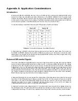
Working with RS422 and RS485 devices is not much different from working with standard RS232 serial 
devices and these two standards overcome deficiencies in the RS232 standard. First, the cable length 
between two RS232 devices must be short; less than 50 feet at 9600 baud. Second, many RS232 errors 
are the result of noise induced on the cables. The RS422 standard permits cable lengths up to 5000 feet 
and, because it operates in the differential mode, it is more immune to induced noise. 
  
Connections between two RS422 devices (with CTS ignored) should be as follows: 


Device #1


Device #2


Signal 

Pin No.

Signal 

Pin No. 

Gnd 5 Gnd  5 

TX

+

2 RX

+

TX

-

3 RX

-

RX

+

9 TX

+

RX

-

1 TX

-


Table A-1:

 Connections Between Two RS422 Devices 


A third deficiency of RS232 is that more than two devices cannot share the same cable. This is also true 
for RS422 but RS485 offers all the benefits of RS422 plus allows up to 32 devices to share the same 
twisted pairs. An exception to the foregoing is that multiple RS422 devices can share a single cable if only 
one will talk and the others will all receive. 


Balanced Differential Signals

  
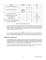
The reason that RS422 and RS485 devices can drive longer lines with more noise immunity than RS232 
devices is that a balanced differential drive method is used. In a balanced differential system, the voltage 
produced by the driver appears across a pair of wires. A balanced line driver will produce a differential 
voltage from +2 to +6 volts across its output terminals. A balanced line driver can also have an input 
"enable" signal that connects the driver to its output terminals. If the "enable signal is OFF, the driver is 
disconnected from the transmission line. This disconnected or disabled condition is usually referred to as 
the "tristate" condition and represents a high impedance. RS485 drivers must have this control capability. 
RS422 drivers may have this control but it is not always required. 


A balanced differential line receiver senses the voltage state of the transmission line across the two signal 
input lines. If the differential input voltage is greater than +200 mV, the receiver will provide a specific 
logic state on its output. If the differential voltage input is less than -200 mV, the receiver will provide the 
opposite logic state on its output. A maximum operating voltage range is from +6V to -6V allows for 
voltage attenuation that can occur on long transmission cables.  
  
A maximum common mode voltage rating of +7V provides good noise immunity from voltages induced on 
the twisted pair lines. The signal ground line connection is necessary in order to keep the common mode 
voltage within that range. The circuit may operate without the ground connection but may not be reliable. 


Manual PCI-ICM-1S 

17

Summary of Contents for PCI-ICM-1S

Page 1: ...MODEL PCI ICM 1S USER MANUAL FILE MPCI ICM 1S C1c...

Page 2: ...l nor the rights of others IBM PC PC XT and PC AT are registered trademarks of the International Business Machines Corporation Printed in USA Copyright 2000 2005 by Portwell I O Products Inc All right...

Page 3: ...anty Warranty commences with equipment shipment Following Years Throughout your equipment s lifetime Portwell stands ready to provide on site or in plant service at reasonable rates similar to those o...

Page 4: ...ap 11 Chapter 4 Address Selection 12 Chapter 5 Programming 13 Table 5 1 Baud Rate Divisor Values 13 Chapter 6 Connector Pin Assignments 16 Table 6 1 Connector Pin Assignments 16 Table 6 2 Data Cable W...

Page 5: ...y COM Port Compatibility A type 16550 UART is used as the Asynchronous Communication Element ACE It includes a 16 byte FIFO transmit receive buffer to protect against lost data in multitasking operati...

Page 6: ...control feature the card is ideal for use in Windows applications Specification Communications Interface I O Connection 9 Pin DBM Connector Character length 5 6 7 or 8 bits Parity Even odd or none Sto...

Page 7: ...Figure 1 1 Block Diagram Manual PCI ICM 1S 7...

Page 8: ...tallation The following instructions assume the CD ROM drive is drive D Please substitute the appropriate drive letter for your system as necessary DOS 1 Place the CD into your CD ROM drive 2 Type B t...

Page 9: ...ws 3 1 or any other non PNP compliant operating system should set the PNP CMOS option to BIOS or Motherboard Save the option and continue booting the system 9 Most computers should auto detect the car...

Page 10: ...o 115 200 baud When in the 4x position the baud rate range is up to 460 800 baud Note Refer to Table 5 1 Baud Rate Divisor Values Termination Jumpers A transmission line should be terminated at the re...

Page 11: ...x1 x4 BAUD 485 422 DB9M TRM OUT TRM IN 4 80 3 30 Figure 3 2 Option Selection Map Manual PCI ICM 1S 11...

Page 12: ...operating systems Windows95 98 2000 can be queried to determine which resources were assigned In these operating systems you can use either PCIFind DOS or PCINT Windows95 98 NT or the Device Manager u...

Page 13: ...position the UART clock frequency is 1 8432 Mhz When the jumper is in the X4 position the clock frequency is 7 3728 MHz The following table lists popular divisor frequencies Note that there are two co...

Page 14: ...ever data are ready to be read from the chip A simple polling loop must continuously check this bit and read in data as it becomes available The following code fragment implements a polling loop and u...

Page 15: ...atically enables the transmitter when data are ready to send No software enabling is required The following C code fragment demonstrates this process while data i While there is data to send while inp...

Page 16: ...6 1 Connector Pin Assignments The following table shows pin connections between two devices for Simplex Half Duplex and Full Duplex operations Mode Card 1 Card 2 Rx pin 9 Tx pin 2 Simplex 2 wire rece...

Page 17: ...erential drive method is used In a balanced differential system the voltage produced by the driver appears across a pair of wires A balanced line driver will produce a differential voltage from 2 to 6...

Page 18: ...that end Note You do not have to add a terminator resistor to your cables when you use the PCI ICM 1S card Termination resistors for the RX and RX lines are provided on the card and are placed in the...

Page 19: ...that one node be a master node and all others be slaves The network is connected so that the master communicates to all slaves and all slaves communicate only with the master This has advantages in eq...

Page 20: ...any problems with this manual or just want to give us some feedback please email us at tech portwell com Please detail any errors you find and include your mailing address so that we can send you any...

Reviews: