


6- ENG
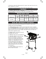
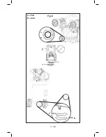
basIc aIR coMPRessoR coMPonents
The basic components of the air compressor are the electric motor, pump,
pressure switch and tank (see
Fig. 1).
The
electric motor
(see
a
) powers the pump. The electric motor is equipped
with an
overload protector
to help prevent possible motor burnout. If the motor
becomes overheated, the overload protector will shut it down. Should this occur,
allow the motor to cool for 10-15 minutes, then press (never force) the motor
reset switch to restart the motor.
The
pump
(see
b
) compresses the air and
discharges it into the tank.
The
tank
(see
c
) stores the compressed air.
The
pressure switch
(see
D
) shuts down
the motor and relieves air pressure in
the pump and transfer tube when the air
pressure in the tank reaches the kick–out
pressure. As compressed air is used
and the pressure level in the tank drops
to the kick–in pressure, the pressure
switch restarts the motor automatically,
without warning and the pump resumes
compressing air.
The
air line outlet
(see
e
). Connect 1/4”
NPT air hose to this outlet.
Fig. 1
waRnIng
sPecIfIcatIon cHaRt
calIfoRnIa PRoPosItIon 65 waRnIng:
This product contains chemicals
known to the State of California to cause cancer, birth defects and/or
reproductive harm.
MoDel no.
RunnIng
H.P.
tanK
caPacIty
gallons
Voltage/
aMPs/
PHase
KIcK-In
PRessuRe
KIcK-out
PRessuRe
PXCM301
1.6
30 (113,6)
120
15
1
125
(8,6 bar)
155
(10,7 bar)
6. Protect the air hose from damage and puncture. Inspect them weekly for weak or worn
spots, and replace if necessary.
7. To reduce the risk of electric shock, do not expose to rain. Store indoors.
A
E
C
B
D
Summary of Contents for PXCM301
Page 12: ...12 ENG A Full B Add Fig 6 OPEN CLOSE F E...
Page 35: ...35 FR A Plein B Ajoutez Fig 6 F E OUVERT FERM...
Page 59: ...59 SP Fig 6 F E A Lleno B Agregor ABIERTO SE CIERRAN...
Page 74: ...NOTES...
Page 75: ...NOTES...


