background image

13

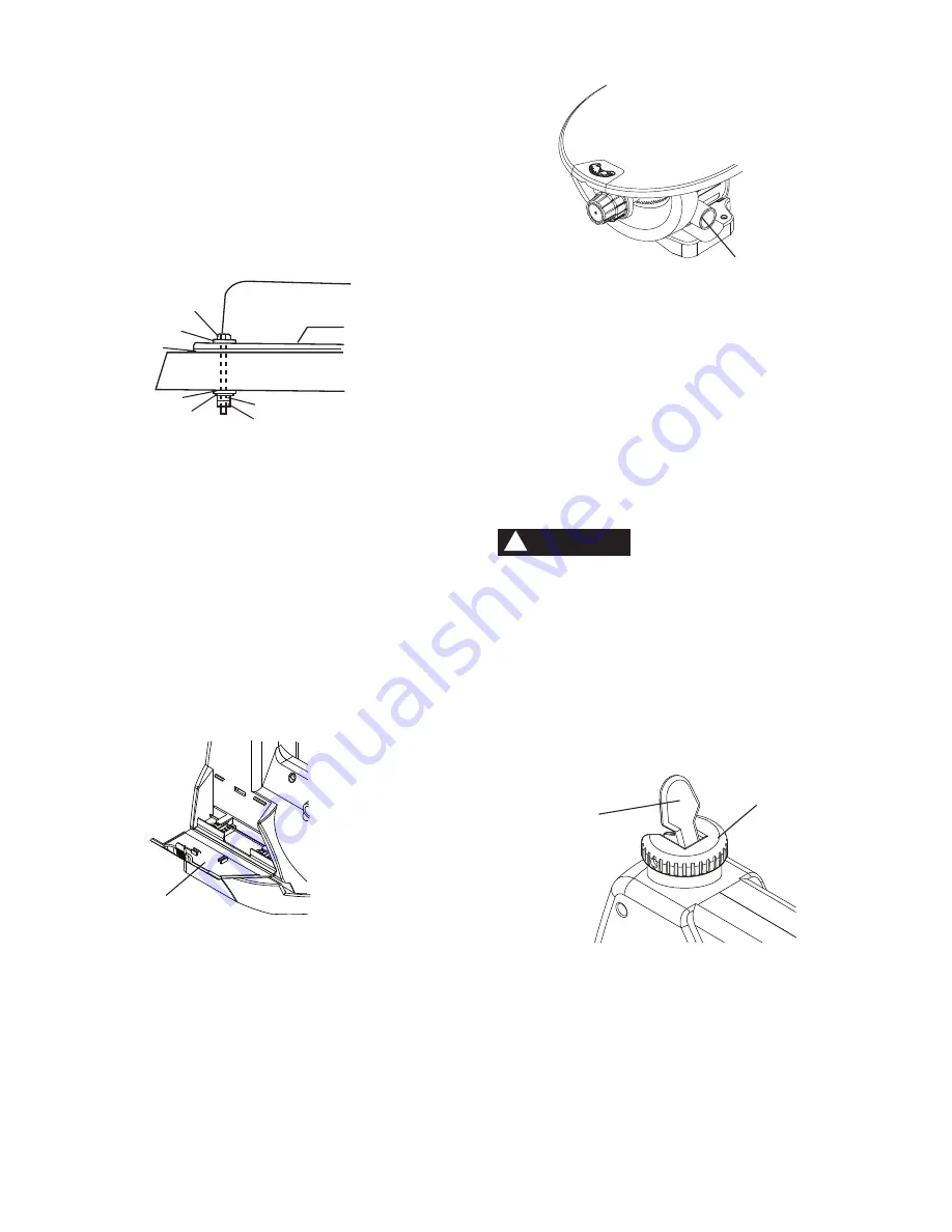
MOUNTING SCROLL SAW TO WORK SURFACE
(FIG. C)

1.  If mounting the scroll saw to a workbench, a solid 

wood bench is preferred over a plywood board to 
reduce noise and vibration.

2.  The hardware to mount this saw is NOT supplied with 

the saw. The hardware as shown in Fig. C should be 
used:


   Fig. C


1.  (3) Hex head bolts; length as required
2.  (6) Flat washers
3.  Foam pad or carpet (optional)
4.  (3) Lock washers
5.  (3) Hex nuts
6.  (3) Jam nuts

BLADE STORAGE (FIG. D)

Blade storage is located on the left rear side of the scroll 
saw body. Pull out the blade storage door (1) to open. 
The compartment can conveniently store your hex 
wrenches and both Pin-end and Plain-end blades.

     Fig. D

SAWDUST COLLECTION PORT (FIG. E)

This scroll saw will accept a hose or vacuum accessory 
(not provided) to be connected to the port (1) on the 
right side of base. If excessive sawdust buildup occurs 
inside the base, use a wet /dry vacuum cleaner or 
manually remove sawdust by removing the screws on 
the left side of saw. Reattach the metal plate and screws 
before starting the saw. This will keep your saw cutting 
efficiently.

1

2

3

5

6

2

4

1

     Fig. E

BLADE REMOVAL AND INSTALLATION

PLAIN-END BLADE REMOVAL AND INSTALLATION

This scroll saw accepts 5-inch (127 mm) Plain-end or 
Pin-end blades to cut a wide variety of materials.

Plain-end type blades are recommended whenever fine, 
accurate and intricate work is being performed on 3/4 in. 
(19 mm) or thinner material. It will take slightly longer to 
assemble the blade and blade tension, but you will also 
be able to use finer blades for cutting a thinner kerf.

To avoid injury from accidental starting, always turn 
the switch OFF (O) and remove power cord plug 
from power source before removing or replacing the 
blade.

Plain-end blade removal (FIG. F, G, H)

1.  To remove the blade (1-Fig. G), loosen the blade 

tension by lifting the quick release tension lever 
(2-Fig. F).

Fig. F

2.  Loosen the upper blade holder (3) by turning the 

blade holder lock knob (4) counterclockwise. (Fig. G)

     NOTE:

 The hex set screw (5) on the left side is used 

     for fine adjustments and is only adjusted if the blade   
     is not perpendicular to the table.

1

WARNING

!

2

1

Summary of Contents for PCB370SS

Page 1: ...RRA CALADORA DE VELOCIDAD VARIABLE DE 406 MM 16 PULG CATALOG NUMBER PCB370SS Instruction Manual Manuel d instructions Manual de instrucciones www portercable com INSTRUCTIVO DE OPERACI N CENTROS DE SE...

Page 2: ...tection Use a separate electrical circuit for your tools The scroll saw is wired at the factory for 110 120 Volt operation It must be connected to a 120V 1 6 AMP branch circuit and use a 1 6 AMP time...

Page 3: ...DS AWAY FROM THE MOVING PART AND CUTTING SURFACE Failure to keep your hands away from the moving part and cutting surface will result in serious personal injury SUPPORT AND CLAMP WORK Some dust create...

Page 4: ...Goggles not glasses that comply with ANSI Safety standard Z87 1 Everyday eyeglasses have only impact resistant lenses They ARE NOT safety glasses NOTE Glasses or goggles not in compliance with WARNIN...

Page 5: ...ble when the saw is in operation 12 TO PREVENT INJURIES avoid awkward hand or nger positions where a sudden slip could cause a hand to move into the blade when operating the saw 13 HOLD WORKPIECE FIRM...

Page 6: ...ged or worn cords immediately WARNING WARNING Use a separate electrical circuit for your tool This circuit must not be less than 18 wire and should be protected with a 1 6 Amp time lag fuse Before con...

Page 7: ...the receptacle is properly grounded If you are not sure have a quali ed electrician check the receptacle CAUTION Fig 1 Fig 2 Three Pronged Plug Grounding Prong Properly Grounded Three Pronged Receptac...

Page 8: ...The scroll saw is heavy and should be lifted with care If needed get the assistance of someone to lift and move the scroll saw If any part is missing or damaged do not attempt to assemble the scroll...

Page 9: ...9 UNPACKING YOUR SCROLL SAW OFF A B E H F G C D...

Page 10: ...oot lock knob Upper arm Blade guard foot Quick release tension lever Blade storage Tension knob Stand Blade lock knob Sawdust collection port ON OFF switch Work light Table lock knob Bevel scale Blade...

Page 11: ...he table at the angle desired for bevel cutting VARIABLE SPEED ON OFF CONTROL KNOB Variable switch dial allows greater versatility when cutting a variety of materials Adjust the speed to the desired s...

Page 12: ...Place stand on level surface and adjust so all legs are contacting the oor and are at similar angles to the oor and detents in stand leg align with support brackets then tighten all bolts NOTE To avoi...

Page 13: ...e left side of saw Reattach the metal plate and screws before starting the saw This will keep your saw cutting ef ciently 1 2 3 5 6 2 4 1 Fig E BLADE REMOVAL AND INSTALLATION PLAIN END BLADE REMOVAL A...

Page 14: ...tly by using a hex wrench through the screw 13 5 Tighten the tension on the blade by turning the tension knob 15 clockwise Check the tension on the blade If too loose turn knob clockwise Fig J Overtig...

Page 15: ...g M 2 Make sure the pins are properly located in the upper 4 and the lower 3 blade holders Fig M 3 To tension the blade 1 Fig M lower the quick release tension lever 5 Check the tension on the blade I...

Page 16: ...for the best use of blades and speeds on various materials Use this table as an example but practice and your own personal preference will determine the best selection method 1 2 WARNING Fig Q TEETH I...

Page 17: ...h as wood plastics non ferrous metals etc Depending on the hardness and thickness of material the speed should be reduced to allow the blade teeth to remove cut material from the kerf VARIABLE SPEED C...

Page 18: ...6 4 mm thick or less Use wider blades for thicker materials but this will reduce the ability to cut tight curves 11 This saw uses 5 in 127 mm long pin or plain end type blades 12 Blades wear faster w...

Page 19: ...check your measurements using the workpiece to be cut and make sure the scrap wood 6 is secure 4 Position the workpiece against the blade and place the blade guard foot 1 slightly above the top surfac...

Page 20: ...workpiece on the saw table with the workpiece hole 4 over the access hole in the table 5 4 Install the blade 3 through the hole in the workpiece and lower the quick release tension lever 2 5 Follow th...

Page 21: ...on An occasional coat of paste wax on the work table will allow the wood being cut to glide smoothly across the work surface To avoid shock or re hazard if the power lead is worn or cut in any way rep...

Page 22: ...y only Porter Cable recommended accessories should be used with this product A complete line of accessories is available from your Porter Cable Factory Service Center or a Porter Cable Authorized Warr...

Page 23: ...BLADE REMOVAL AND INSTALLATION section 2 Reduce feed rate See BLADE REMOVAL AND INSTALLATION section 3 Use narrow blade See BLADE SELECTION section 4 Avoid side pressure on blade See BLADE REMOVAL AN...

Page 24: ...ER ASS Y 1 0JUZ HEX SOC HD CAP BOLT M8 1 25 40 1 2XRP ROCKER SWITCH 2 0JVD HEX SOC HD CAP BOLT M5 0 8 35 1 2XRQ LEAD WIRE ASS Y 1 0JXR HEX SOC SET SCREW M8 1 25 8 1 2XSE LAMP ASS Y 1 0K23 HEX SOC HD C...

Page 25: ...AE 0C10 0C12 0U7V 2 20XY 0J4U 0GXQ 0GXR 0KQX 0KDR 0GXP 4 4 2ECC 0KQY 2XZA 0K2B 3 0DF6 2 0DF8 0K56 0K70 2XRE 0ZX3 0ZX1 0ES8 2XZ7 2XRP 2AN9 0KDM 2YQB 3 0KBC 2XZ2 2 2XZK 2 2YPQ 2YPJ 2Y1Y 2Y1Z 0KA9 2 0JB0...

Page 26: ...SUPPORT 6 2 2LBM SHORT UPPER SUPPORT 6 2 2LBN LEG 6 4 2LBP LONG BOTTOM SUPPORT BRACKET 6 2 2LBQ SHORT BOTTOM SUPPORT BRACKET 6 2 2LD2 STAND ASS Y 1 2LQT CUSHION 4 2YPN WARNING LABEL 1 HARDWARE BAG 2L...

Page 27: ...27 NOTE...

Page 28: ...trademarks for one or more Porter Cable and Delta products 2 BY 4 890TM Air America AIRBOSSTM Auto Set B O S S Bammer Biesemeyer Builders Saw Charge Air Charge Air Pro CONTRACTOR SUPERDUTY Contractor...

Reviews: