9
WARNING:
Always make sure the wheel guard is positioned
between operator and the wheel, so that flying chips or pieces of a
wheel that might break will be deflected away from the operator (see
Fig. 3).
TO INSTALL GRINDING WHEEL
1.
CAUTION:
DISCONNECT MACHINE FROM POWER CIRCUIT.
2.
Rest machine on its back with spindle facing up.
3.
Install and adjust the appropriate wheel guard following instructions in
TO INSTALL WHEEL GUARD Section of this manual.
4.
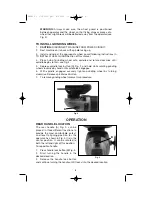
Place hub of grinding wheel onto spindle and rotate clockwise until
spindle begins to turn, see Fig. 4.
5.
Depress spindle lock button (D) Fig. 2, and hold while rotating grinding
wheel clockwise by hand until spindle lock engages.
6.
With spindle engaged securely tighten grinding wheel by turning
clockwise. Release spindle lock button.
7.
To remove grinding wheel reverse this procedure.
OPERATION
REAR HANDLE LOCATION
The rear handle (A) Fig. 5, can be
placed in three different locations to
provide the most comfortable, safest,
and least fatiguing position for the
operator. As shown in Fig. 5 it is in the
center position. It can be rotated to
both the left and right of this position.
To reposition handle:
1.
Press handle lock button (B) Fig. 5.
2.
Start turning the handle in the
desired direction.
3.
Release the handle lock button
and continue turning the handle until it locks into the desired location.
Fig. 5
B
D
Fig. 4
283800 - 07-31-00.QXD 9/23/02 1:34 PM Page 9

