9
E l e c t r i c a l E q u i p m e n t
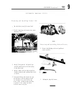
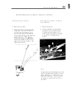
R e m o v i n g a n d I n s t a l l i n g C l u t c h
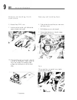
R e m o v i n g a n d I n s t a l l i n g S e r v o
P e d a l S w i t c h
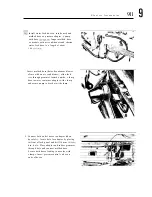
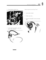
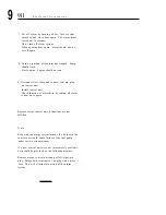
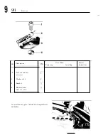
1. Remove front
cover.
1. Take out hose between heater air connection
and blower motor.
2. Unscrew nuts on bracket, pull off wires and
remove bracket with switch.
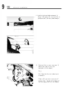
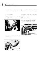
2. Pull off plugs on servo and solenoid.
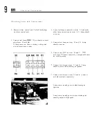
When installing make sure switch is adjusted
correctly for clutch pedal. Adjust bracket in
slots so that switch is not damaged when
pulling back clutch pedal t o check clutch
3.
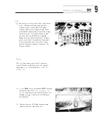
Unscrew mounting screws, detach vacuum
line (small hose) on servo.
N o t e
The vacuum hose is connected to an adaptor
near the throttle housing.
Summary of Contents for 1972 911
Page 1: ...Workshop manual DR ING h c F PORSCHE KG STUTTGART ZUFFENHAUSEN ...
Page 3: ...Motor und Kupplung Engine and Clutch Moteur et Accouplement Motore e Frizione ...
Page 7: ......
Page 13: ......
Page 14: ......
Page 16: ...D e s c r i p t i o n 9 1 1 1 ...
Page 20: ......
Page 21: ...D e s c r i p t i o n ...
Page 22: ...D e s c r i p t i o n 911 1 ...
Page 25: ...9 1 1 T e c h n i c a l D a t a ...
Page 30: ...Horsepower Output Ne DIN HP b ...
Page 31: ...911 T e c h n i c a l D a t a Full power Performan s C1L Engine Speed n rpm vJ ...
Page 33: ...T e c h n i c a l D a t a 911 1 Full power Performance Carrera Q Engine Speed n rpm a ...
Page 39: ...c i a a 911 1 ...
Page 40: ...fl T e c h n i c a l D a t a ...
Page 41: ...ine Speed n rpml W V ...
Page 44: ...T e c h n i c a l D a t a 911 1 ...
Page 56: ...C o o l i n g S y s t e m Exhaust System E m i s s i o n C o n t r o l 9 4 3 11 0 Z W ffi ...
Page 57: ......
Page 97: ...C a m s h a f t H o u s i n g a n d C y l i n d e r H e a d 911 ...
Page 143: ...REMOVING A N D I N S T A L L I N G T H R O W O U T BEARING ...
Page 147: ...C L U T C H M O D I F I C A T I O N S 1 9 7 8 M O D E L S ...
Page 149: ...Kraftstoffanlage Fuel System Systeme d alimentation Sistema d alimentazione ...
Page 155: ...D e s c r i p t i o n ...
Page 164: ......
Page 169: ......
Page 202: ...V A C U U M S Y S T E M L A Y O U T 1 9 7 8 M o d e l s ...
Page 213: ...S e r v i c i n g 3 I I 2 D I S A S S E M B L I N G A N D R E A S S E M B L I N G ...
Page 217: ......
Page 230: ...R e p a i r s D I S M A N T L I N G A N D ASSEMBLING M I X T U R E C O N T R O L U N I T ...
Page 280: ...Getriebe Transmission Bo itede Vitesses Cambio ...
Page 285: ...3 911 M a n u a l T r a n s m i s s i o n I ...
Page 291: ...911 T r a n s m i s s i o n ...
Page 298: ......
Page 300: ...o t o t i 911 3 ...
Page 305: ...S p o r t o m a t i c ...
Page 309: ...Transmission Diagram 5 speed transmission Ring Ratio 7 31 ...
Page 310: ...Transmission Diagram 4 speed transmission Pinion to Ring Ratio 7 31 Type 915 Transmission ...
Page 318: ...I T e c h n i c a l D a t a ...
Page 321: ...T e c h n i c a l D a t a 911 ...
Page 325: ...TransmissionDiagram 5 speed transmission Pinion to Rlng Ratio 8 31 Type 915 44 Transmission ...
Page 327: ...T e c h n i c a l D a t a 911 ...
Page 331: ...T e c h n i c a l D a t a 911 ...
Page 333: ......
Page 336: ...TransmissionDiagram Sportomatic Pinion to Ring Ratio 8 27 Type 925 09 12 13 Transmission ...
Page 339: ......
Page 359: ...D i s a s s e m b l y a n d R e a s s e m b l y ...
Page 386: ...911 M a n u a l T r a n s m i s s i o n ...
Page 395: ...M a n u a l T r a n s m i s s i o n 9 1 1 3 RELEASE LEVER 1 9 7 8 M O D E L S ...
Page 421: ...S p o r t o m a t i c Disassembling and Assembling Transmission ...
Page 430: ...911 S p o r t o m a t i c Disassembling and Assembling Transmission Front Cover ...
Page 433: ...S p o r t o m a t i c 9 1 1 3 4 Install shift rod seal with special tool P 218 ...
Page 442: ...9 1 1 S p o r t o m a t i c D I S M A N T L I N G A N D A S S E M B L I N G ...
Page 446: ...D I S M A N T L I N G A N D A S S E M B L I N G ...
Page 464: ...911 F i n a l D r i v e M a n u a l T r a n s m i s s i o n ...
Page 468: ......
Page 486: ...Vorderachse Front Axle ssieu AV Assale anteriore ...
Page 501: ...REMOVING A N D I N S T A L L I G F R O N T AXLE BALL J O I N T ...
Page 507: ...911 F r o n t A x l e D I S A S S E M B L Y A N D R E A S S E B L Y ...
Page 512: ...911 S t e e r i n g W h e e l a n d S t e e r i n g C o l u m n DISASSEMBLY A N D REASSEMBLY ...
Page 518: ...Hinterachse Rear Axle Essieu AR Assale posteriore ...
Page 528: ...5 911 R e a r A x l e DISASSEMBLY A N D REASSEMBLY ...
Page 537: ...Brernsen Rader Reifen Brakes Wheels Tires Freins Roues Pneus Freni Ruote Gomme ...
Page 544: ...B r a k e s W h e e l s T i r e s 911 6 REMOVING A N D I N S T A L L I N G BRAKE BOOSTER ...
Page 563: ...Hebelwerk Pedal System and Levers Pedalier et Leviers Pedaleria e Leve ...
Page 567: ...D I S A S S E M B L I N G A N D A S S E M B L I N G S H I F T LEVER ASSEMBLY ...
Page 573: ...D I S A S S E M B L Y A N D REASSEMBLY ...
Page 586: ...11 P e d a l C o n t r o l s D I S A S S E M B L I N G A N D R E A S S E M B L I N G ...
Page 592: ...7 911 P e d a l C o n t r o l s D I S A S S E M B L Y A N D REASSEMBLY ...
Page 601: ...Aufbau Body Carrosserie Carrozzeria ...
Page 614: ...B u m p e r s 911 F R O N T B U M P E R S E F F E C T I V E W I T H 1 9 7 4 M O D E L S ...
Page 618: ...B u m p e r s 9 1 1 8 R E A R BUMPER E F F E C T I V E W I T H 1 9 7 4 M O D E L S ...
Page 625: ...Rear L i d w i t h S p o i l e r 911 8 ...
Page 648: ......
Page 722: ...F l o o r P a n e l A s s e m b l y D i m e n s i o n s 50 ...
Page 746: ...53 B o d y R e a r B O D Y R E P A I R S R E A R ...
Page 755: ...Elektrische Anlage Electrical System Installation electrique lmpianto elettrico ...
Page 777: ...Current flow diagram Type 911USA Model 74 9 ...
Page 781: ...Additional current flow diagram CIS injection and Sportomatic Type 911 Model 74 9 ...
Page 783: ...Current flow diagram Type 911USA Model 75 9 ...
Page 785: ...Current flow diagram Type 911USA Model 75 ...
Page 789: ...Additional current flow diagram headlight washers Type 911 ...
Page 794: ...Additional current flow diagram power windows Type 911 ...
Page 797: ...Additional current flow diagram windshield and rear window defoggers Type 911 ...
Page 799: ...Current flow diagram Type 911S USA Model 76 9 ...
Page 800: ......
Page 801: ...Current flow diagram Type 911S USA Model 76 ...
Page 802: ...Additional current flow diagram automatic speed control Type 911 ...
Page 804: ...Additional current flow diagram intermittent wiper operation Model 76 ...
Page 806: ...Additional current flow diagram air conditioner with front condenser ...
Page 808: ...Additional current flow diagram fog lights ...
Page 811: ...Additional current flow diagram remotely controlled outside mirrors Type 911 9 ...
Page 813: ...Current flow diagram Type 911 S USA Model 77 g ...
Page 815: ...Current flow diagram Type 911 S USA Model 77 ...
Page 819: ...Current flow diagram Type 911SC USA Model 78 9 ...
Page 821: ...Current flow diagram 9 Type 911 SC USA Model 78 ...
Page 823: ...Additional current flow diagram power windows Type 911 from model 77 ...
Page 825: ...Additional Current Flow Diagram Air Conditioner M 399 Type 911 from model 77 ...
Page 827: ...AdditionalCurrent Flow Diagram Type 911SCUSA Model 80 Oxygen Sensor System ...
Page 838: ...Current Flow Diagram Type 911 SC USA Model 81 Part W FRESH AIR BLOWER ...
Page 840: ......
Page 841: ...Current Flow Diagram Type 911SC USA Model 81 Part VI OXYGENSENSOR SYSTEM ...
Page 842: ......
Page 854: ......
Page 856: ...Current Row Diagram Type 911 SC USA Model82 Part IV 1 5 bk FRESH AIR BLOWER ...
Page 858: ...Current Flow Diagram Type 911 SC USA Model82 Part V ...
Page 859: ...Current Flow Diagram Type 911 SC USA Model 82 Part VI OXYGEN SENSOR SYSTEM HEADLIGHT WASHER ...
Page 871: ...D i s a s s e m b l i n g a n d A s s e m b l i n g S t a r t e r ...
Page 984: ......


