background image


S

YSTEM 

L

AYOUT


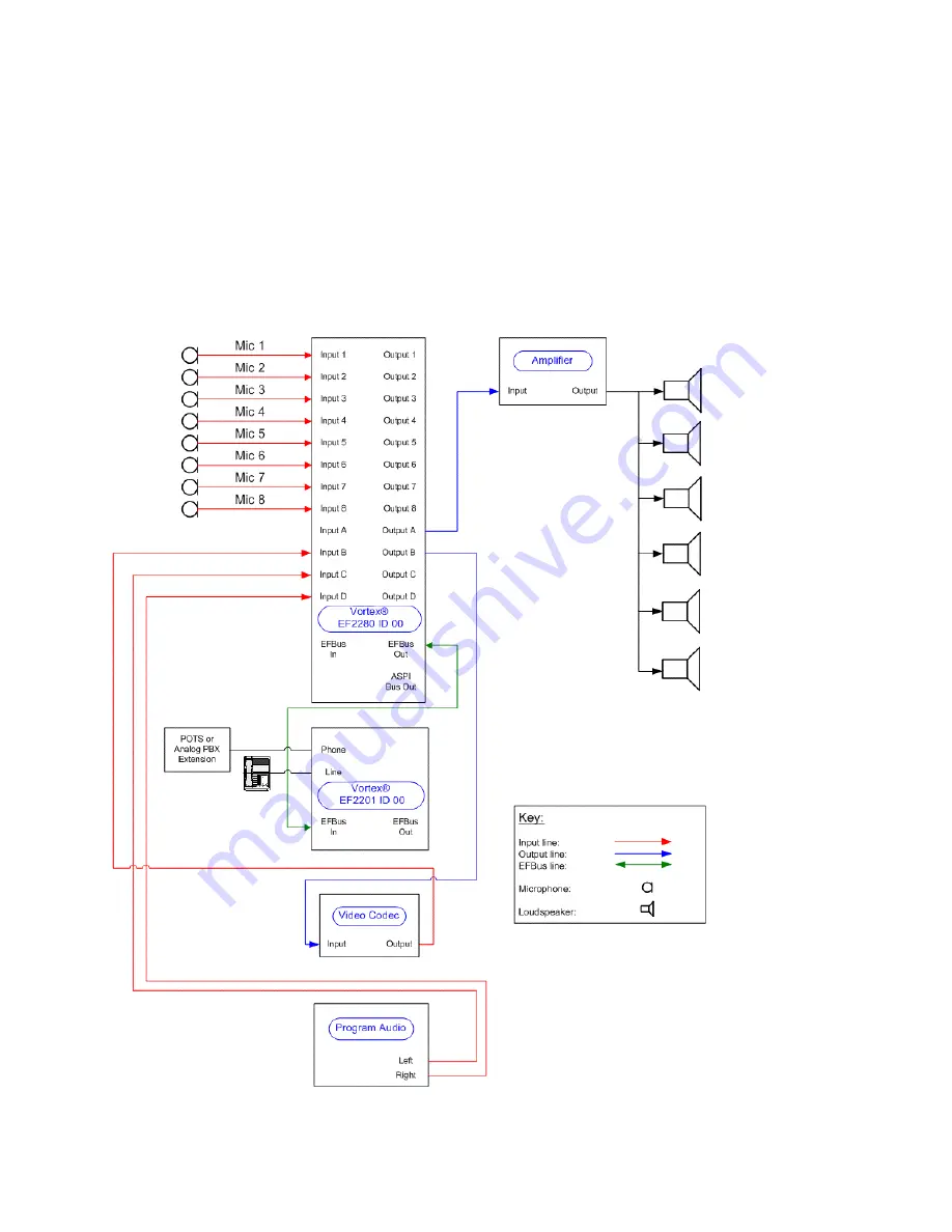
The audio components for the room are 8 tabletop microphones, 1 EF2280, 1 EF2201, 1 video codec, 1 
amplifier, 1 program audio source, and 6 ceiling loudspeakers.   Each of the microphones will use Inputs 1-
8.  The video codec will use Input B / Output B.  The program source will use Inputs B and C.  The amplifier 
will use Output A.


69

Summary of Contents for Vortex EF2241

Page 1: ...Interfacing Vortex Devices to Video Codecs Application Note Polycom Installed Voice Business Group Revision I September 2004 ...

Page 2: ... and Outputs 13 Setting the AEC Reference Using an iPower 900 15 Testing the Audio Inputs and Outputs 16 INPUT OUTPUT TESTING 16 LOOPBACK TESTING 17 Wiring from iPower to Vortex Device 18 INPUT TO IPOWER FROM OUTPUT OF VORTEX DEVICE USING CBL LINEAUDIO 18 INPUT TO IPOWER FROM OUTPUT OF VORTEX DEVICE USING SELF MADE CABLE 18 OUTPUT OF IPOWER TO INPUT OF VORTEX DEVICE 19 PowerMic Cable Pinout 19 POL...

Page 3: ...g the AEC Reference Using a ViewStation EX 35 Testing the Audio Inputs and Outputs 35 Wiring from ViewStation EX to Vortex Device 36 INPUT TO VIEWSTATION EX FROM OUTPUT OF VORTEX DEVICE 36 OUTPUT OF VIEWSTATION EX TO INPUT OF VORTEX DEVICE 36 Tips for ViewStation EX 36 POLYCOM VIEWSTATION FX 37 Connecting the ViewStation FX Inputs and Outputs 37 Setting the AEC Reference Using a ViewStation FX 39 ...

Page 4: ...vels 55 Gain Structure for Line Input Sources 56 Testing the Audio Inputs and Outputs 56 Controlling a Vortex Device via the VSX 8000 57 1 Enable Vortex Mixer as an RS 232 Option in the VSX 8000 57 2 Create the Appropriate Macros in the Vortex Device s Muting 58 Volume Control Codec Only 59 Volume Control Codec and Telephone 62 3 Verify that the VSX 8000 Remote Control properly controls the Vortex...

Page 5: ...MATRIX MIXER 71 PRESETS 73 Conference Composer Layout EF2201 74 EFBUS 74 PRESETS 75 TECHNICAL SUPPORT 77 Polycom Installed Voice Business group Contact Information 77 5 ...

Page 6: ...ou may order one by contacing your Polycom reseller and requesting part number CBL LINEAUDIO You can also make your own cable Click here for instructions 2 Connect the line level output of the codec to one of the line level inputs of the Vortex device Inputs A D You may use one of the Mic Line level inputs but you need to disable all processing on that input AEC AGC NC Automixer disable Phantom Po...

Page 7: ...7 ...

Page 8: ...iate Output of the Vortex device to 10 dB It is important to set the gain structure correctly so that you don t clip the input audio stage of the codec and that the Vortex device gets a good signal to perform processing with The nominal input and output of the codec is 3 V rms The nominal input and output of the Vortex device is 775 V rms This equates to a difference of 8 24 dB between the two nom...

Page 9: ...r the Help file in Conference ComposerTM for more information 3 Turn on the white noise generator in the Vortex device and assign it to the output that will be sent to the iPower If the output gain of the Vortex device is set to 10 set the crosspoint to 55 This is required because if the input of the iPower does not detect a signal it will turn on the built in microphone Since the internal echo ca...

Page 10: ...MIC LINE INPUTS MATRIX MIXER 10 ...

Page 11: ...d read Step 3 WIRING FROM IPOWER TO VORTEX DEVICE The inputs and outputs to the codec are unbalanced We recommend keeping the cable from the Vortex device as short as possible to avoid any common mode signals that may corrupt the audio INPUT TO IPOWER FROM OUTPUT OF VORTEX DEVICE USING CBL LINEAUDIO If you are using CBL LINEAUDIO connect the Positive conductor of the Vortex device to the Tip of th...

Page 12: ...e You first need a 7 pin Mini DIN connector Most electronic supply houses should carry this connector Once you ve obtained the connector connect the Positive conductor from the Vortex device to Pin 7 of the DIN connector Connect the Negative conductor from the Vortex device to Pin 4 of the DIN connector Do not connect the shield of the cable to the DIN connector The PowerMic input is unbalanced in...

Page 13: ... contacing your Polycom reseller and requesting part number CBL LINEAUDIO You can also make your own cable See the section labeled PowerMic Cable Pinout for instructions 2 Connect the line level output of the codec to one of the line level inputs of the Vortex device Inputs A D You may use one of the Mic Line level inputs but you need to disable all processing on that input AEC AGC NC Automixer di...

Page 14: ...als sent and received from the codec 3 Raise the gain on the appropriate Input of the Vortex device to 10 dB 4 Lower the gain on the appropriate Output of the Vortex device to 10 dB It is important to set the gain structure correctly so that you don t clip the input audio stage of the codec and that the Vortex device gets a good signal to perform processing 14 ...

Page 15: ...EC REFERENCE USING AN IPOWER 900 1 Open AdminTools there should be a shortcut on the desktop select the Audio Category and click on the Audio Inputs tab De select Use Echo Cancellation Use Noise Suppression and Use Automatic Gain Control AGC 2 Make sure that the Input to the Vortex device is assigned to the appropriate AEC Reference signal Consult the Reference Manual for the Vortex device or the ...

Page 16: ...Diagnostics The shortcut should be located in the PROGRAMS POLYCOM IPOWER ADMINISTRATOR INFORMATION folder Select TEST AUDIO To test the input to the codec select MICROPHONE A V BOARD You should see level activity for the left channel only Set the INPUT VOLUME to halfway 16 ...

Page 17: ...successful loopback test with the iPower 900 Series either all ISDN lines must be connected or all ISDN lines must be disconnected If the ISDN lines are connected or disconnected a reboot is needed prior to making a loopback call 1 Place a call with 0000000 seven zeroes and click on Call Now button 2 Once the call has finished connecting you should see and hear yourself 17 ...

Page 18: ... are using CBL LINEAUDIO connect the Positive conductor of the Vortex device to the Tip of the RCA connector and the Negative conductor of the Vortex device to Shield of the RCA connector The shield of the cable is not connected INPUT TO IPOWER FROM OUTPUT OF VORTEX DEVICE USING SELF MADE CABLE Connect the Positive conductor of the Vortex device to Pin 7 of DIN connector and the Negative conductor...

Page 19: ...werMic Interface Cable You first need a 7 pin Mini DIN connector Most electronic supply houses should carry this connector Once you ve obtained the connector connect the Positive conductor from the Vortex device to Pin 7 of the DIN connector Connect the Negative conductor from the Vortex device to Pin 4 of the DIN connector Do not connect the shield of the cable to the DIN connector The PowerMic i...

Page 20: ...nputs A C signals Do not use the PowerMic Input to send audio into the codec 2 Connect the left channel line level output of the codec colored white to one of the line level inputs of the Vortex device Inputs A D You may use one of the Mic Line level inputs but you need to disable all processing on that input AEC AGC NC Automixer disable Phantom Power and set the input to line level versus the def...

Page 21: ...Please follow our instructions for wiring the Vortex device to the codec Failure to do so may induce noise into the signals sent and received from the codec 21 ...

Page 22: ...rform processing with The nominal input and output of the codec is 3 V rms The nominal input and output of the Vortex device is 775 V rms This equates to a difference of 8 24 dB between the two nominal levels For simplicity you may round that value to 10 dB DISABLING READINESS MONITOR MICROPHONE ERROR MESSAGES After the codec is installed the Readiness Monitor will alert you to the fact that a Pow...

Page 23: ...ing box open ADMINTOOLS there may be a shortcut on the desktop otherwise the shortcut should be located under the Administrator Information folder select UTILITIES and click on the READINESS MONITORING tab De select MICROPHONE S 23 ...

Page 24: ...nd click on the AUDIO INPUTS tab De select USE ECHO CANCELLATION USE NOISE SUPPRESSION and USE AUTOMATIC GAIN CONTROL AGC 2 Make sure that the Input to the Vortex device is assigned to the appropriate AEC Reference signal Consult the Reference Manual for the Vortex device or the Help file in Conference Composer for more information 24 ...

Page 25: ...iagnostics The shortcut should be located in the PROGRAMS POLYCOM IPOWER ADMINISTRATOR INFORMATION folder Select TEST AUDIO To test the input to the codec select AUXILIARY AUDIO You should see level activity for the left and right channels Set the INPUT VOLUME to halfway 25 ...

Page 26: ... tick mark from the top This represents approximately 12 dB LOOPBACK TESTING In order to run this test you simply press the Call Add Button as you would with any other test call and you dial a string 0000000 Seven Zeros and then press the Call Now Button At this point the call will negotiate and you will see and hear yourself in a Loopback 26 ...

Page 27: ...TEX Connect the Positive conductor of the Vortex device to the Tip of the RCA connector and the Negative conductor of the Vortex device to Shield of the RCA connector The shield of the cable is not connected OUTPUT OF IPOWER TO INPUT OF VORTEX DEVICE Connect the Positive conductor of the Vortex device to the Tip of the RCA connector and the Negative conductor of the Vortex device to Shield of the ...

Page 28: ...128 H 323 MP 512 INPUTS AND OUTPUTS In order to send and receive audio to the Polycom ViewStation 128 H 323 MP or 512 codec you need to observe the following procedure 1 Make sure that the ViewStation codec has firmware version 7 5 or higher installed in it You can find this information on the System Info page We do not recommend using a ViewStation 128 H 323 MP or 512 codec with a Vortex device u...

Page 29: ... inputs but you need to disable all processing on that input AEC AGC NC Automixer disable Phantom Power and set the input to line level versus the default of mic level Follow the diagram below to make the proper physical connections to the codec Do not use any other audio inputs or outputs as they could cause an audio loopback to occur within the codec 29 ...

Page 30: ... good signal to perform processing with The nominal input and output of the codec is 3 V rms The nominal input and output of the Vortex device is 775 V rms This equates to a difference of 8 24 dB between the two nominal levels For simplicity you may round that value to 10 dB SETTING THE AEC REFERENCE USING A VIEWSTATION 128 H 323 MP 512 1 Connect a monitor to Output 1 of the codec By default the c...

Page 31: ...S NEAR END LOOP 3 Go to SYSTEM INFO DIAGNOSTICS AUDIO GENERATE TONE to listen to a codec generated 1 kHz tone 4 Go to SYSTEM INFO ADMIN SETUP PHONE AUDIO and un check the ECHO CANCELLER option WIRING FROM VIEWSTATION 128 H 323 MP 512 TO VORTEX DEVICE The inputs and outputs to most codecs are unbalanced We recommend keeping the cable from the Vortex device as short as possible to avoid any common m...

Page 32: ...trol is too low Since the local participants heard the sound effects audio at a normal level it may not be obvious that the volume control is set too low The sound effects volume control can be adjusted in the SYSTEM INFO ADMIN SETUP PHONE AUDIO page 2 If the ViewStation codec is turned off either through the power switch or unplugged from the wall while the codec is still connected to the Vortex ...

Page 33: ...f the Inputs A C signals 4 Connect the auxiliary line level output of the codec to one of the line level inputs of the Vortex device Inputs A D You may use one of the Mic Line level inputs but you need to disable all processing on that input AEC AGC NC Automixer disable Phantom Power and set the input to line level versus the default of mic level Follow the diagram below to make the proper physica...

Page 34: ...t is sent from the far side will be monaural Please follow our instructions for wiring the Vortex device to the codec See Wiring from ViewStation EX to Vortex device Failure to do so may induce noise into the signals sent and received from the codec 5 Raise the gain on the appropriate Input of the Vortex device to 10 dB 34 ...

Page 35: ...the screen about disabling the echo canceller and select OK 6 Once that is completed make sure that the Input to the Vortex device is assigned to the appropriate AEC Reference signal Consult Reference Manual for the Vortex device or the Help file in Conference Composer for more information TESTING THE AUDIO INPUTS AND OUTPUTS 2 Go to SYSTEM INFO ADMIN SETUP PHONE AUDIO and check the ECHO CANCELLER...

Page 36: ...uctor of the Vortex device to Shield of the RCA connector The shield of the cable is not connected TIPS FOR VIEWSTATION EX 1 The volume control for the ViewStation EX controls the incoming far side audio and the local tone generator It does not however control the sound effects inside the units such as incoming call ring and the female speech that occurs when you dial a number This is important to...

Page 37: ...l feed the input of the codec or the input channel of the Vortex device that is connected to the output of the codec Polycom ViewStation FX CONNECTING THE VIEWSTATION FX INPUTS AND OUTPUTS In order to send and receive audio to the Polycom ViewStation FX codec you need to observe the following procedure 1 Connect one of the Outputs of the Vortex device to the mixer input of the codec By default Out...

Page 38: ...t to the Vortex device Any audio that is sent from the far side will be monaural Please follow our instructions for wiring the Vortex device to the codec See Wiring from ViewStation FX to Vortex device Failure to do so may induce noise into the signals sent and received from the codec 38 ...

Page 39: ... and check the ECHO CANCELLER option Ignore the warning that is displayed on the screen about disabling the echo canceller and select OK 3 Once that is completed make sure that the Input to the Vortex device is assigned to the appropriate AEC Reference signal Consult Reference Manual for the Vortex device or the Help file in Conference Composer for more information TESTING THE AUDIO INPUTS AND OUT...

Page 40: ... INPUT TO VIEWSTATION FX FROM OUTPUT OF VORTEX DEVICE Connect the Positive conductor of the Vortex device to the Tip of the RCA connector and the Negative conductor of the Vortex device to Shield of the RCA connector The shield of the cable is not connected OUTPUT OF VIEWSTATION FX TO INPUT OF VORTEX DEVICE Connect the Positive conductor of the Vortex device to the Tip of the RCA connector and the...

Page 41: ...ol is set too low The sound effects volume control can be adjusted in the System Info Admin Setup Phone Audio page 2 If the ViewStation FX is turned off either through the power switch or unplugged from the wall while the codec is still connected to the Vortex device via the input and output audio cables a loopback will occur in the codec This means that a portion of the audio signal that is sent ...

Page 42: ... A C signals 2 Connect the auxiliary line level output of the codec to one of the line level inputs of the Vortex device Inputs A D You may use one of the Mic Line level inputs but you need to disable all processing on that input AEC AGC NC Automixer disable Phantom Power and set the input to line level versus the default of mic level Follow the diagram below to make the proper physical connection...

Page 43: ...43 ...

Page 44: ...ood signal to perform processing with The nominal input and output of the codec is 3 V rms The nominal input and output of the Vortex device is 775 V rms This equates to a difference of 8 24 dB between the two nominal levels For simplicity you may round that value to 10 dB SETTING THE AEC REFERENCE USING A VS4000 1 Connect a monitor to Output 1 of the codec By default the composite output is enabl...

Page 45: ...M INFO DIAGNOSTICS NEAR END LOOP 3 Go to SYSTEM INFO DIAGNOSTICS AUDIO GENERATE TONE to listen to a codec generated 1 kHz tone 4 Go to SYSTEM INFO ADMIN SETUP PHONE AUDIO and un check the ECHO CANCELLER option WIRING FROM VS4000 TO VORTEX DEVICE The inputs and outputs to most codecs are unbalanced We recommend keeping the cable from the Vortex device as short as possible to avoid any common mode s...

Page 46: ...ch as incoming call ring and the female speech that occurs when you dial a number This is important to note because if the volume control is very low it may appear that the codec audio is fine because the sound effects are still generated and will be heard in the local room However when a call is connected the local side may not hear the far side because the local volume control is too low Since t...

Page 47: ...nput of the codec By default Outputs A C of the Vortex device are mix minus versions of the Inputs A C signals 2 Connect the auxiliary line level output of the codec to one of the line level inputs of the Vortex device Inputs A D You may use one of the Mic Line level inputs but you need to disable all processing on that input AEC AGC NC Automixer disable Phantom Power and set the input to line lev...

Page 48: ...48 ...

Page 49: ... may round that value to 10 dB ENABLING THE VSX 7000 TO WORK WITH A VORTEX DEVICE We recommend that the firmware version of the VSX 7000 be updated to at least 7 0 or higher because the internal VSX 7000 echo canceller can be disabled 1 Connect a monitor to the video output of the codec 2 Go to System Admin Settings Audio Settings and select NEXT for Page 2 Select the AUDIO MIXER option for the Li...

Page 50: ...EVICE The inputs and outputs to most codecs are unbalanced We recommend keeping the cable from the Vortex device as short as possible to avoid any common mode signals that may corrupt the audio INPUT TO VSX 7000 FROM OUTPUT OF VORTEX DEVICE Connect the Positive conductor of the Vortex device to the Tip of the RCA connector and the Negative conductor of the Vortex device to Shield of the RCA connec...

Page 51: ... the volume control is set too low The sound effects volume control can be adjusted in the System Admin Settings Audio Settings page 2 If the VSX 7000 is turned off either through the power switch or unplugged from the wall while the codec is still connected to the Vortex device via the input and output audio cables a loopback will occur in the codec This means that a portion of the audio signal t...

Page 52: ... are mix minus versions of the Inputs A B or C signals respectively Any of these signals can be used with the default factory preset on the Vortex If you are using Polycom InstantDesigner choose the input and output that InstantDesigner recommends 2 Connect the auxiliary line level output of the codec to one of the line level inputs of the Vortex device Inputs A D If you have more line inputs you ...

Page 53: ...Connecting the VSX 8000 to a Vortex EF2241 53 ...

Page 54: ...tting to 5 3 Optional Enable the VSX 8000 to control the Vortex Device by setting Serial Port 1 or Serial Port 2 to Vortex Mixer In the VSX 8000 User Interface go to SYSTEM ADMIN SETTINGS GENERAL SETTINGS SERIAL PORTS For the appropriate port select VORTEX MIXER for RS 232 Mode Verify that the baud rate of the VSX 8000 matches the baud rate of the Vortex Device See the page CONTROLLING A VORTEX DE...

Page 55: ...mately 30 dB Based on the transmit level you may need to apply gain in the Vortex Device For example if a wireless receiver s nominal transmit level is 10 dB you will need to apply 10 dB on the input of the Vortex Device to achieve unity 0 dB gain In order to set the gain appropriately we recommend leaving all processing enabled and having someone talk into the microphone Have another person watch...

Page 56: ...hat value to 10 dB Therefore the inputs of the Vortex that receive consumer level outputs need to be set to 10 dB in order to achieve a unity gain The outputs of the Vortex will be about 10 dB too high for the consumer level equipment and in turn need to be set to 10 dB to avoid clipping and to maintain enough headroom in the consumer level devices The Input gain of a Vortex device that is connect...

Page 57: ...ontrol a Vortex Device The Volume Up button will send a MACROX183 command to Serial Port 1 or 2 and the Volume Down button will send a MACROX184 command to Serial Port 1 or 2 Here are three steps to follow in order to set up this functionality 1 ENABLE VORTEX MIXER AS AN RS 232 OPTION IN THE VSX 8000 In the VSX 8000 User Interface go to SYSTEM ADMIN SETTINGS GENERAL SETTINGS SERIAL PORTS For the a...

Page 58: ... Go to Vortex System Settings on the LCD display select the Enter key and use the Up or Down buttons to scroll until you see Baud Rate Once that parameter is set use the Up or Down buttons to scroll until you see Flow Control 2 CREATE THE APPROPRIATE MACROS IN THE VORTEX DEVICE S MUTING As previously mentioned the Mute button on the Remote Control sends a command to execute Macro 180 and Macro 181...

Page 59: ...cro 181 repeat the same steps as for Macro 180 except that the Mute for Inputs 1 4 should be off When you are finished you should see this If there are more inputs on other Vortex Devices in your system that need to be muted and unmuted repeat these steps for the appropriate inputs VOLUME CONTROL CODEC ONLY To use the Vortex Device to perform volume control first set the VSX 8000 s Balanced Output...

Page 60: ... how to write a Volume Control Macro for a system that has the VSX 8000 connected to Input A of a Vortex Device Inside the Vortex Device Input A is routed to Output B and to R1 The Macros should control the cross point gains to Output B and to the R1 reference bus so that the room gain stays consistent for increasing volume First label Macro 183 as Volume Up and Macro 184 as Volume Down Next inser...

Page 61: ...successful you should see this in the window Next add the cross point control for R1 Click Insert Command Matrix A From VSX 8000 R1 Reference 1 Gain 1 dB If you are successful you should see this in the window 61 ...

Page 62: ...0 connected to Input A of a Vortex Device and a built in telephone hybrid on Input T Inside the Vortex Device Input A and Input T are routed to Output B and to the reference R1 The Macros should control the cross point gains for Inputs A and T to Output B and to the R1 reference bus so that the room gain stays as the volume is increased First follow the directions given in the VOLUME CONTROL CODEC...

Page 63: ...on the signal generator in the VSX 8000 User Interface Go to System Info Diagnostics Audio Speaker Test If there are multiple linked Vortex Devices in the system you can perform the same series of steps or you can connect your computer to the RS 232 port of the second Vortex device run Conference Composer autoscan and open a Console Window in Conference Composer by right clicking on the Comm port ...

Page 64: ...wn buttons if you have assigned commands to Macro s 183 and 184 For more information on setting up the VSX 8000 with a Vortex device including stereo operation gated mixer settings and more please see the Application Note Vortex VSX 8000 Integration 64 ...

Page 65: ...r wiring the Vortex device to the codec Failure to do so may induce noise into the signals sent and received from the codec 3 Raise the gain on the appropriate Input of the Vortex device to 10 dB 4 Lower the gain on the appropriate Output of the Vortex device to 10 dB 5 Go to AUDIO SETTINGS INPUT LEVEL SETTINGS and set the gain on the proper Input to 0 dB 6 Go to AUDIO SETTINGS OUTPUT LEVEL SETTIN...

Page 66: ...put 6 depending on which Input is connected to the Vortex device Once that is completed make sure that the Input to the Vortex device is assigned to the appropriate AEC Reference signal Consult the Reference Manual for the Vortex device or the Help file in Conference Composer for more information WIRING FROM CODEC TO VORTEX DEVICE The inputs and outputs to most codecs are unbalanced We recommend k...

Page 67: ...T OF VORTEX DEVICE Connect the Positive conductor of the Vortex device to the Tip of the RCA connector and the Negative conductor of the Vortex device to Shield of the RCA connector The shield of the cable is not connected 67 ...

Page 68: ...ates a 24 ft X 38 ft X 10 ft conference room that has 8 tabletop microphones and 6 ceiling loudspeakers The system includes a EF2280 matrix mixer an EF2201 telephone hybrid a video codec and a program audio source There is no sound reinforcement in this room 68 ...

Page 69: ...crophones 1 EF2280 1 EF2201 1 video codec 1 amplifier 1 program audio source and 6 ceiling loudspeakers Each of the microphones will use Inputs 1 8 The video codec will use Input B Output B The program source will use Inputs B and C The amplifier will use Output A 69 ...

Page 70: ...f the default parameters of the EF2280 will satisfy our design such as microphone gains and automixer settings However we will need to re label the EFBus for clarity and change the Matrix Mixer and Presets to satisfy our design goals EFBUS 70 ...

Page 71: ...ease 6 dB in gain Mathematically two signals of 1V peak to peak amplitude are added together the result is a signal of 2V peak to peak In terms of decibels that can be expressed as 20 log 2V 1V which equals 6 dB Inputs B and C are reduced by 10 dB to Output Y because if a program source is mixed at 0 dB with local speech it may be difficult for the remote person on the telephone to distinguish bet...

Page 72: ...Local Microphones should NEVER be included the reference signal 72 ...

Page 73: ...reset 16 although you may use any of the User Presets 16 47 to accomplish this task We ve also renamed User Preset 16 to Conference Room Once the User Preset has been saved you must also change the Power on Preset to reflect the proper Preset that you want the unit to power up to if the unit loses AC power 73 ...

Page 74: ...Most of the default parameters of the EF2201 will satisfy our design such as microphone gains and automixer settings However we will need to need to re label the EFBus for clarity and change Presets to satisfy our design goals EFBUS 74 ...

Page 75: ...e EFBus is put into a placeholder where that placeholder is identified by the Device ID of the unit that put the audio signal into this placeholder Here the EF2280 placed audio onto the W and Y buses and since the unit has a device ID of 00 the placeholder is identified as WB0 and YB0 where the B stands for bus The EF2201 takes that signal from the bus and internally assigns that signal to one of ...

Page 76: ...t 16 although you may use any of the User Presets 16 47 to accomplish this task We ve also renamed User Preset 16 to Conference Room Once the User Preset has been saved you must also change the Power on Preset to reflect the proper Preset that you want the unit to power up to if the unit loses AC power 76 ...

Page 77: ...cal support dial 1 800 POLYCOM POLYCOM INSTALLED VOICE BUSINESS GROUP CONTACT INFORMATION Our address is 9040 Roswell Road Suite 450 Atlanta GA 30350 770 350 4140 Phone 770 350 4142 Fax Copyright 2004 Polycom Inc Polycom the Polycom logo Vortex and ViewStation are registered trademarks and Conference Composer VS4000 iPower and VSX are trademarks of Polycom Inc in the USA and various countries All ...

Reviews: