Polycom 55

Setting Up Your Display Using Plug and Play

This display adheres to VESA Plug and Play standard to eliminate complicated and time 

consuming setup of displays. This display identifies itself to the computer and automatically 

sends the PC its Extended Display Identification Data (EDID) using Display Data Channel

(DDC) protocols.

How To Set Up Your  Display with PC (Windows)

The display settings for a typical Windows-based computer are shown below; however, 

actual screens on your computer will differ depending on the version of Windows and video 

equipped with the computer. Even though the actual screen may look different from example

displayed below, basic set-up routine will apply in most cases.

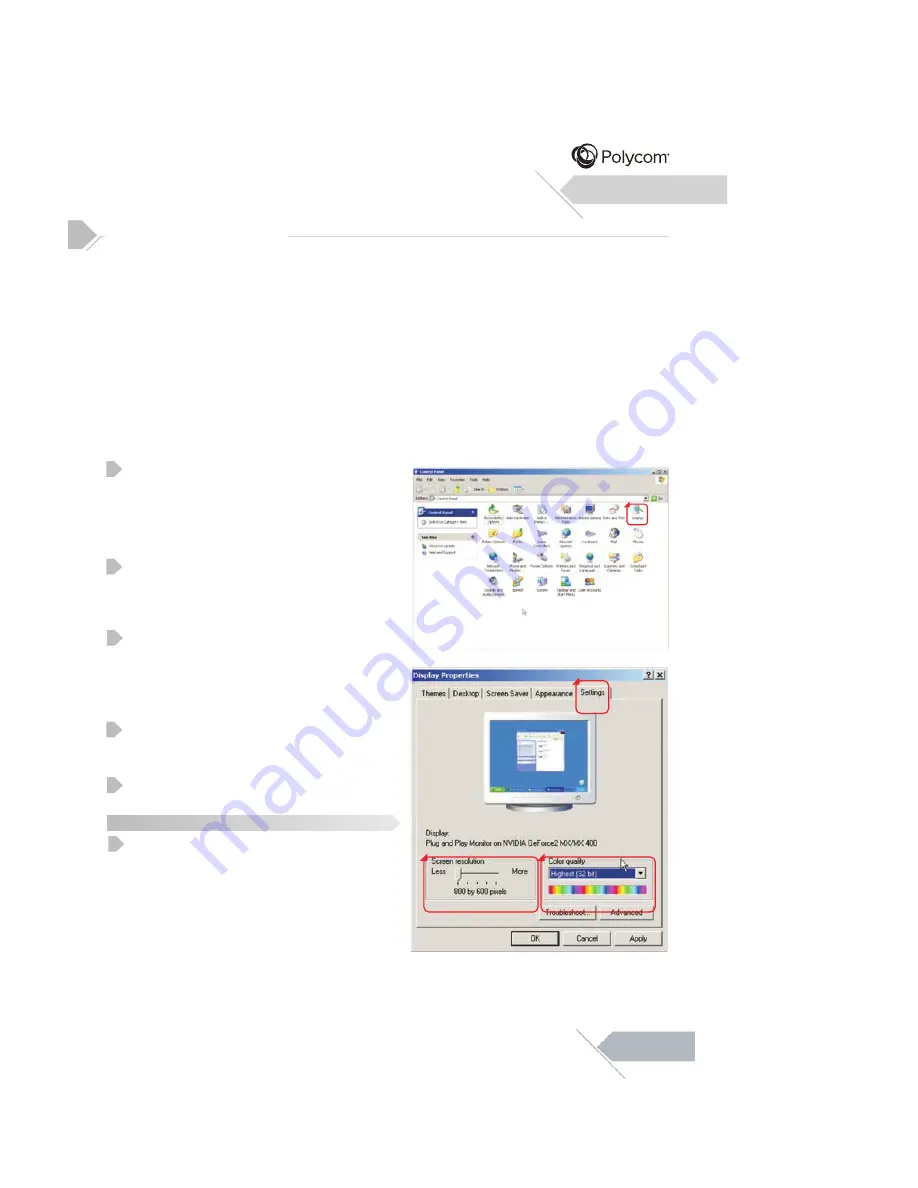
Go to Window’s CONTROL PANEL by 

clicking: START, SETTINGS, CONTROL 

PANEL. The CONTROL PANEL Window is 

displayed. Select the DISPLAY icon from this 

window. 
The DISPLAY PROPERTIES dialog box is 

displayed. Select the SETTINGS tab to 

display your computer’s video output settings.

Set the “Screen Resolution” setting to 

1920x1080p PIXELS. For COLOR QUALITY, 

select 24 BIT COLOR (might also be 

expressed as 16 million colors).

If a vertical-frequency option exists, set the 

value to 60Hz.

Click OK to complete the setting.

Note:

Both screen position and size will vary, 

depending on the type of PC graphics card 

and  its resolution selected.

Connecting a PC (con’t)

1

2

3

4

5

Installation

1

2

3

4

1

12

Summary of Contents for 55" LED DISPLAY

Page 1: ...55 LED DISPLAY...

Page 2: ...ial Notices 11 14 15 14 16 16 Fine Tuning Under RGB HDMI Mode Specifications Dimensional Drawings 18 18 19 23 25 26 25 Supported Resolutions Explanation of Various Picture Control Settings Command For...

Page 3: ...ur r duire le risque de choc lectrique ne pas retirer les couvercles avant ou arri re Aucune pi ce n est r parable par l utilisateur Confiez l entretien du personnel qualifi Risk of Electric Shock Do...

Page 4: ...icular installation If this equipment does cause harmful interference to radio or television receptions which can be determined by turning the equipment off and on the user is encouraged to try to cor...

Page 5: ...05...

Page 6: ...Turns power on from standby mode There is a wait period between on standby cycles Adjustment Buttons Select Buttons Use these buttons to navigate through the On Screen Display menu Menu Button Use th...

Page 7: ...a Codec or PC video connector The USB port is labelled It is provided for after service engineer use ONLY RJ 45 07...

Page 8: ...08...

Page 9: ...regarding the operation status of when OSD picture vanishes To access the OSD menu press MENU button on the remote control or on the rear cover Navigation through the OSD menu can be accomplished by u...

Page 10: ...10...

Page 11: ...PC Connecting an External Amplifier Connecting an External Amplified Speaker 11...

Page 12: ...actual screen may look different from example displayed below basic set up routine will apply in most cases Go to Window s CONTROL PANEL by clicking START SETTINGS CONTROL PANEL The CONTROL PANEL Wind...

Page 13: ...13...

Page 14: ...s and is applicable to all video inputs As such many of the adjustment sub settings are grayed out and are not accessible to the user In order to make adjustments to these settings CUSTOM picture mode...

Page 15: ...Picture Quality Adjustment RGB HDMI Mode Picture Quality Adjustment RGB Mode NOISE REDUCTION HDMI RGB RANGE until your video picture is optimal Increasing 15...

Page 16: ...p menu default setting is 1 minute When using HDMI or RGB input After the display has entered sleep mode due to inactivity absence of active video the display will automatically turn back on when the...

Page 17: ...Menu System Explanation of Various System Settings 17 AUTO POWER DOWN AUTO POWER DOWN...

Page 18: ...Additional Information will cause a permanent 18...

Page 19: ...Specifications Additional Information RJ 45 19 120 Watts Max 1 2A Max...

Page 20: ...Specifications Additional Information 20...

Page 21: ...Specifications Additional Information Audio Output only for HDMI Audio Input 3dB The MTBF is 60 000 hrs back light 1243 6mm 63 9mm 714 4mm 63 94lbs 29kgs 79 37lbs 36kgs 21...

Page 22: ...Specifications Additional Information 22...

Page 23: ...Additional Information 23 RJ 45 Connection RJ 45 RJ 45 RJ 45 Putty Putty...

Page 24: ...RGA GGA BGA ROF GOF BOF IPS IPC PON Power On OFF Power Off CNM Mild VVD Vivid PLC Polycom mode USR Custom 001 100 001 100 001 100 001 100 001 100 MID Natural HIG Cool 65D Warm USR Custom CP1 COMP RG1...

Page 25: ...Dimensional Drawings Additional Information Item Color Scheme Outer Front Bezel Black 25...

Page 26: ...03Y1 B 6 SPAKA0918Y1 8 SPAKC0962Y1 7 10 JHNDP0020Y1 11 YTIE P155Y1600 9 TLABD1142Y1 A TINSE2240Y1 YRC 294POLYCOMC RBATB0226Y1DD SSAKD0003Y1 T C 1 1 1 1 1 1 1 1 1 1 1 ACCESSORY KIT ACCESSORY KIT ACCESS...

Reviews: