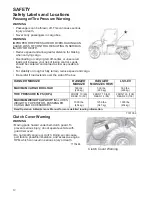
background image

22

FEATURES AND CONTROLS

Console

Auxiliary Outlet

The 12-volt receptacle has spade connections on the back that may be used to power an 
auxiliary light or other optional accessories or lights. The connections are behind the 
console, under the hood.

Mode Button

The yellow button located near the instrument cluster is used to toggle through mode options 
available. See pages 30-34.

Ignition Switch/Light Switch

The ignition switch is a four-position, key-operated switch. The key can be removed from 
the switch when it is in the OFF position.

OFF

The engine is off. Electrical circuits are off, except Acc, 12V.

LIGHTS ON

Lights are on. Electrical circuits are on. Electrical equipment can be used.

LIGHTS OFF

Lights are off. Electrical circuits are on. Electrical equipment can be used.

START

Turn the key to the START position to engage the electric starter. Turn the key 
to the LIGHTS ON position after starting the engine.

12V Auxiliary

Outlet

Storage

Tray

Instrument 

Cluster

Gear Selector 

(Shifter)

Storage

Compartment

Cup

Holder

Ignition/Light 

Switch

AWD 

Switch

Steering Wheel 

Adjustment

Lever

MODE

Button

Summary of Contents for RANGER 570 EPS

Page 1: ...Owner s Manual for Maintenance and Safety RANGER ETX RANGER 570 RANGER 570 EPS RANGER CREW 570 RANGER CREW 570 EPS...

Page 2: ...e safety precautions could result in serious injury or death WARNING The engine exhaust from this product contains chemicals known to the State of California to cause cancer birth defects or other rep...

Page 3: ...and recreational vehicles manufactured in the world today Many years of experience have gone into the engineering design and development of your POLARIS vehicle making it the finest machine we ve ever...

Page 4: ...l vehicle and the information presented in this publication Depictions and or procedures in this publication are intended for reference use only No liability can be accepted for omissions or inaccurac...

Page 5: ...Introduction 4 Safety 8 Features and Controls 21 Operation 35 Winch Guide 49 Emission Control Systems 58 Maintenance 59 Specifications 90 POLARIS Products 92 Troubleshooting 93 Warranty 96 Maintenanc...

Page 6: ...ential personal injury hazard DANGER A DANGER indicates a hazardous situation that if not avoided will result in death or serious injury WARNING A WARNING indicates a hazardous situation that if not a...

Page 7: ...fety DVD and take the free online Recreational Off Highway Vehicle Association ROHVA training course at www rohva org This vehicle is an ADULT VEHICLE ONLY You MUST be at least age 16 and have a valid...

Page 8: ...e of your existing keys The ignition switch must be replaced if all keys are lost Vehicle Model Number ________________________________________________________________________ Frame VIN ______________...

Page 9: ...condition The environment was controlled as indicated by the test procedure s The uncertainty of vibration exposure measurement is dependent on many factors including Instrument and calibration uncert...

Page 10: ...a helmet that meets or exceeds established safety standards Approved helmets in the USA and Canada bear a U S Department of Transportation DOT label Approved helmets in Europe Asia and Oceania bear th...

Page 11: ...nd protection Never ride a POLARIS vehicle with bare feet or sandals Clothing Wear long sleeves and long pants to protect arms and legs Rider Comfort Under certain operating conditions heat generated...

Page 12: ...ment Replacement safety labels are provided by POLARIS at no charge The part number is printed on the label Max Payload Warning WARNING 7181296 Shift Caution CAUTION To avoid transmission damage shift...

Page 13: ...s Pay Attention and Plan Ahead If you think or feel the vehicle may tip or roll reduce your risk to injury Keep a firm grip on the steering wheel or hand holds and brace yourself Do not put any part o...

Page 14: ...ul if load extends over the side of the box 7181056 Clutch Cover Warning WARNING Moving parts hazard under belt clutch guard To prevent serious injury do not operate vehicle with guard removed Do not...

Page 15: ...over the ankle boots and seat belt at all times Always use the cab nets or doors while riding in this vehicle Always keep hands and feet inside the vehicle at all times Always keep both hands on the s...

Page 16: ...s manual for traveling downhill and for braking on hills See page 40 Check the terrain carefully before descending a hill Never travel downhill at high speed Avoid going downhill at an angle which wou...

Page 17: ...ge 18 for fuel safety warnings Always remove the ignition key when the vehicle is not in use to prevent unauthorized use by someone under the age of 16 or without a driver s license and proper trainin...

Page 18: ...on different types of terrain All operators must read and understand the Owner s Manual and all warning and instruction labels before operating the vehicle All operators should review the safety DVD p...

Page 19: ...Vehicle The weight of both cargo and passengers impacts vehicle operation For your safety and the safety of others carefully consider how your vehicle is loaded and how to safely operate the vehicle...

Page 20: ...chemicals known to cause cancer birth defects or other reproductive harm Operate this vehicle only outdoors or in well ventilated areas Operating a Damaged Vehicle Operating a damaged vehicle can resu...

Page 21: ...familiar terrain may contain hidden rocks bumps or holes that could cause loss of control or rollover Travel slowly and use extra caution when operating on unfamiliar terrain Always be alert to changi...

Page 22: ...cle and or the operator fall through the ice Never operate the vehicle on a frozen body of water unless you have first verified that the ice is sufficiently thick to support the weight and moving forc...

Page 23: ...cab nets are only to allow component identification Always use the cab nets or doors Not all models come with all features Refer to the specifications section beginning on page 90 ROPSCab Frame Hip B...

Page 24: ...key operated switch The key can be removed from the switch when it is in the OFF position OFF The engine is off Electrical circuits are off except Acc 12V LIGHTS ON Lights are on Electrical circuits a...

Page 25: ...enter position to lock the differential and operate in two wheel drive 2WD See page 48 for Differential Lock operating instructions Press the bottom of the switch to unlock the differential and allow...

Page 26: ...pt to shift gears with engine speed above idle or while the vehicle is moving Tip Maintaining shift linkage adjustment is important to assure proper transmission function See your dealer if you experi...

Page 27: ...se switch which is designed to reduce the risk of a frozen or stuck throttle If the throttle cable should stick in an open position when the operator releases the throttle pedal engine speed will be l...

Page 28: ...lectronic Power Steering EPS Electronic power steering if equipped engages when the ignition key is turned to the ON position EPS remains engaged whether the vehicle is moving or idle To conserve batt...

Page 29: ...chest Make sure the belt is not twisted 2 Push the latch plate into the buckle until it clicks 3 Release the strap it will self tighten 4 To release the seat belt press the square red button in the b...

Page 30: ...traps Promptly replace worn or dam aged cab nets and latches with new cab nets and latches Please see your authorized POLARIS dealer Securing a Net 1 After entering the vehicle insert the lower net ro...

Page 31: ...with a receiver hitch bracket for a trailer hitch Trailer towing equipment is not supplied with this vehicle To avoid injury and property damage always heed the warnings and towing capacities outline...

Page 32: ...tically reduce engine power EPS Warning This indicator illuminates briefly when the key is turned to the ON position If the light remains on the EPS system is inoperative See your authorized POLARIS d...

Page 33: ...sh Refuel immediately Tip If the fuel icon fails to display an open or short circuit has occurred in the fuel sensor circuit See your dealer 3 Information Display Area This area displays odometer trip...

Page 34: ...play option 5 Repeat the procedure to change remaining display settings Clock Mode Tip The clock must be reset any time the battery has been disconnected or discharged 1 Turn the key to the ON positio...

Page 35: ...he engine is started When this feature is enabled it provides a convenient reminder to perform routine maintenance The service interval is programmed at 50 hours at the factory Use the following proce...

Page 36: ...tes retrieve the error codes from the display 1 If the error codes are not displayed use the MODE button to toggle until Ck ENG displays on the main line of the display 2 Press and hold the MODE butto...

Page 37: ...on page 18 2 Check the oil level See page 62 Add the recommended oil as needed to maintain the oil level in the normal safe operating range 3 Drive slowly at first Select an open area that allows roo...

Page 38: ...ary 61 Steering Ensure free operation 77 Tires Inspect condition and pressure 78 Wheels fasteners Inspect ensure fastener tightness 78 Frame nuts bolts fasteners Inspect ensure tightness Fuel and oil...

Page 39: ...until the engine starts NOTICE Operating the vehicle immediately after starting could cause engine damage Allow the engine to warm up for several minutes before operating the vehicle Stopping the Engi...

Page 40: ...page 36 2 Make sure all passengers are at least 12 years of age and tall enough to comfortably and safely sit in a passenger seat with the seat belt secured put both feet on the floor and grasp the ha...

Page 41: ...Severe damage to the drive train may occur if the AWD is engaged while the wheels are spinning Always allow the wheels to stop spinning before engaging AWD 5 Correct a skid by turning the steering whe...

Page 42: ...te of speed and throttle opening Never open the throttle suddenly 6 Never go over the crest of a hill at high speed An obstacle a sharp drop or another vehicle or person could be on the other side of...

Page 43: ...tacles or people behind the vehicle Always inspect left and right fields of vision before backing 2 Always avoid backing downhill 3 Back slowly 4 Apply the brakes lightly for stopping 5 Avoid turning...

Page 44: ...acles 4 Avoid operating through deep or fast flowing water WARNING The large tires on your RANGER may cause the vehicle to float in deep or fast flowing water which could result in loss of control and...

Page 45: ...e with extra caution Always attach the tow load to the hitch point designated for your vehicle HEAVY LOADS CAN CAUSE BRAKING AND CONTROL PROBLEMS Use extreme caution when applying brakes with a loaded...

Page 46: ...han the recommended weight for the vehicle See the towing capacity chart below and the specifications charts beginning on page 90 6 Attach a trailer to the trailer hitch bracket only Do not attach a t...

Page 47: ...the operator or bystanders Never operate the dump lever without ensuring that the load is positioned evenly or at the front of the box 6 Stand clear and pull up on the cargo box release lever Lift th...

Page 48: ...vehicle may remain in AWD Engaging Disengaging AWD The AWD switch may be turned on or off while the vehicle is moving Press the top of the rocker switch to engage All Wheel Drive Press the bottom of...

Page 49: ...is turned off while the front gearcase is moving it will not disengage until the rear wheels regain traction Engage the AWD before getting into conditions where front wheel drive may be needed If the...

Page 50: ...ing on uneven loose or slippery terrain such as sand gravel ice snow obstacles and water crossings Always operate in AWD on these types of terrain WARNING Operating in TURF mode if equipped when on sl...

Page 51: ...e winch winch cable and load clear of people especially children and distractions while operating the winch 8 Always turn the vehicle ignition power OFF when it and the winch are not being used 9 Alwa...

Page 52: ...un through your hands even if wearing heavy gloves 18 Never release the clutch on the winch when the winch cable is under load 19 Never use the winch for lifting or transporting people 20 Never use th...

Page 53: ...strategy if it is not working Always remember that your winch is very powerful There are simply some situations that you and your winch will not be able to deal with Do not be afraid to ask others to...

Page 54: ...rts available at your authorized POLARIS dealer C If possible keep the winch cable aligned with the centerline of the winching vehicle This will help the spooling of the winch cable and reduce the loa...

Page 55: ...moving when using the winch is when that vehicle itself is stuck The winch equipped vehicle should NEVER be in motion to shock load the winch cable in an attempt to move a second stuck vehicle See th...

Page 56: ...is complete especially if winching at an angle it may be necessary to re distribute the winch cable across the winch drum You will need an assistant to perform this task A Release the clutch on the wi...

Page 57: ...cable has already been permanently and severely damaged Promptly discontinue use of a winch cable in this condition B A kinked winch cable made of wire rope that has been straightened out is shown at...

Page 58: ...ing This puts extra load on the winch winch cable and generates excessive heat from the motor This is a form of shock loading 3 Never tow a vehicle or other object with your winch Towing an object wit...

Page 59: ...tivation of the winch 4 For your safety always replace POLARIS winch parts including the cable with genuine POLARIS replacement parts available at your authorized POLARIS dealer 5 Some winch models us...

Page 60: ...with a closed crankcase system Blow by gases are forced back to the combustion chamber by the intake system All exhaust gases exit through the exhaust system Exhaust Emission Control System Exhaust e...

Page 61: ...inition Frequent immersion in mud water or sand Frequent or prolonged operation in dusty environments Racing or race style high RPM use Prolonged low speed heavy load operation Extended idle Short tri...

Page 62: ...wear 10 H Monthly Inspect periodically Battery 20 H Monthly Check terminals clean test Fuel System 20 H Monthly Inspect cycle key to pressurize fuel pump check lines and fittings for leaks and abrasi...

Page 63: ...ail and fuel pump replace lines every two years Radiator if applicable 100 H 12 M Inspect clean external surfaces Cooling Hoses 100 H 12 M Inspect for leaks Engine mounts 100 H 12 M Inspect Exhaust mu...

Page 64: ...ick area before removing the dipstick Remove the dipstick Wipe it dry with a clean cloth 4 Reinstall and tighten the dipstick 5 Remove the dipstick and check the oil level 6 Add the recommended fluid...

Page 65: ...tely removed 10 Lubricate the o ring on the new filter with a film of fresh engine oil Check to make sure the o ring is in good condition 11 Install the new filter and rotate it clockwise by hand unti...

Page 66: ...cess panel 1 Position the vehicle on a level surface 2 Place the transmission in PARK 3 Always clean away all dirt and debris from the dipstick area before removing the dipstick Remove the dipstick Wi...

Page 67: ...pring retaining the spring for reinstallation 11 Using a clean dry cloth clean the surface of the crankcase 12 Lubricate the o ring for the new filter with a film of fresh engine oil Check to make sur...

Page 68: ...rque to specification Fluid Change The drain plug is located on the bottom of the gearcase Access the drain plug through the hole in the skid plate 1 Remove the fill plug 2 Place a drain pan under the...

Page 69: ...the front gearcase 1 Position the vehicle on a level surface 2 Remove the fill plug Check the oil level 3 Add the recommended oil as needed 4 Reinstall the fill plug Torque to specification Oil Change...

Page 70: ...cap Using the spark plug wrench provided in the tool kit remove the plug by rotating it counter clockwise 3 Reverse the procedure for spark plug installation 4 Torque to specification Normal Plug The...

Page 71: ...e Do not dilute with water See page 92 for the part numbers of POLARIS products To ensure that the coolant maintains its ability to protect the engine we recommend that the system be completely draine...

Page 72: ...t the intervals outlined in the Periodic Maintenance Chart beginning on page 59 Do not obstruct or deflect air flow through the radiator by installing unauthorized accessories in front of the radiator...

Page 73: ...IS products only Do not install it in any other product Always make sure the PVT housing is securely in place during operation Belt Replacement Debris Removal If a belt fails always clean any debris f...

Page 74: ...responsible for creating excessive heat that destroys belts wears clutch components and causes outer clutch covers to fail Switch to low range while operating at slower speeds to extend the life of t...

Page 75: ...8 Take the vehicle to your dealer for service as soon as possible Vehicle Immersion NOTICE If your vehicle becomes immersed major engine damage can result if the machine is not thoroughly inspected Ta...

Page 76: ...and out of the air box 5 With the filter removed clean the intake boot and air box thoroughly and wipe well with a clean dry cloth NOTICE Dirt or debris in the intake boot could result in severe engi...

Page 77: ...or Never go under the vehicle while it s inclined Use the following procedure to periodically purge accumulated carbon from the exhaust pipe 1 Remove the arrester clean out plug located on the bottom...

Page 78: ...tion the vehicle on a level surface 2 View the brake fluid level at the reservoir in the driver s side wheel well The level should be between the upper MAX and lower MIN level lines 3 If the fluid lev...

Page 79: ...e 2 Lightly turn the steering wheel left and right 3 There should be 0 8 1 0 20 25 mm of freeplay 4 If there is excessive freeplay or strange noises or the steering feels rough or catchy have the stee...

Page 80: ...for this vehicle when replacing tires Tire Tread Depth Always replace tires when tread depth is worn to 1 8 3 mm or less Axle and Wheel Nut Torque Specifications Inspect the following items occasiona...

Page 81: ...the tire point toward forward rotation WARNING Improperly installed wheels can adversely affect tire wear and vehicle handling which can result in serious injury or death Always ensure that all nuts...

Page 82: ...nditions until the headlight is replaced Always make sure lights are adjusted properly for best visibility When servicing a halogen lamp don t touch the lamp with bare fingers Oil from your skin leave...

Page 83: ...aced on the wall Include the weight of a rider on the seat while performing this step 5 If a headlight needs adjustment locate the adjustment screw at the back of the headlight 6 Loosen the screw adju...

Page 84: ...con ventional battery A sealed battery can be identified by its flat covers on the top of the bat tery A conventional battery has six filler caps on the top of the battery Always keep battery termina...

Page 85: ...seat rear seat on CREW 570 to access the battery compartment 2 On conventional batteries remove the battery vent tube 3 Disconnect the black battery cable first Disconnect the red battery cable last...

Page 86: ...ld accumulate in an improperly installed vent tube and cause an explosion resulting in serious injury or death Always ensure that the vent tube is free of obstructions and is securely installed as rec...

Page 87: ...oltage WARNING An overheated battery may explode causing severe injury or death Always watch charging times carefully Stop charging if the battery becomes very warm to the touch Allow it to cool befor...

Page 88: ...r reused cloths and pads may contain dirt particles that will scratch the finish Grease all zerk fittings immediately after washing Allow the engine to run for a while to evaporate any water that may...

Page 89: ...on If light rust is found on the chrome finish use steel wool 0000 OTT grade to remove it Gently rub the affected areas with the steel wool until the corrosion has been removed Clean and polish the wh...

Page 90: ...3 tablespoons of engine oil To access the plug holes use a section of clear 1 4 hose and a small plastic squeeze bottle filled with the pre measured amount of oil Do this carefully If you miss the plu...

Page 91: ...ntervals outlined in the Periodic Maintenance Chart beginning on page 59 Transporting the RANGER Follow these procedures when transporting the vehicle 1 Apply the brakes 2 Place the transmission in PA...

Page 92: ...x42x11 5 in 81x107x29 cm 32x42x11 5 in 81x107x 9 cm Ground Clearance 10 in 25 4 cm 10 in 25 4 cm Min Turning Radius 150 in 381 cm 237 in 602 cm Towing Capacity 1500 lbs 680 4 kg 1500 lbs 680 4 kg Hitc...

Page 93: ...58 1 570 9 65 1 ETX 13 58 1 Drive Ratio Front 3 818 1 3 818 1 Tire Size Front 25 x 8 12 25 x 10 12 Tire Size Rear 25 x 11 12 25 x 10 12 Tire Pressure Front 10 psi 69 kPa 10 psi 69 kPa Tire Pressure R...

Page 94: ...Pump for Gallon 3 8 l Jug Coolant 2880514 Antifreeze 50 50 Premix qt 95 l 2880513 Antifreeze 50 50 Premix gal 3 8 l Grease Specialized Lubricants 2871312 Grease Gun Kit All Season Grease 2871322 All S...

Page 95: ...sion to low range and carefully use fast aggressive throt tle application to engage clutch WARNING Excessive throttle may cause loss of control and vehicle roll over Climbing over large objects from a...

Page 96: ...plug and replace if necessary Water or fuel in crankcase Immediately see your POLARIS dealer Low battery voltage Recharge the battery to 12 8 VDC Mechanical failure See your POLARIS dealer Possible C...

Page 97: ...ow or contaminated fuel Add or change fuel clean the fuel system Low octane fuel Replace with recommended fuel Clogged fuel filter See your POLARIS dealer Possible Rich Fuel Cause Solution Fuel is ver...

Page 98: ...nal registration and received the customer copy please contact your dealer immediately NO WARRANTY COVERAGE WILL BE ALLOWED UNLESS YOUR VEHICLE IS REGISTERED WITH POLARIS Initial dealer preparation an...

Page 99: ...S AVAILABLE TO ANY PERSON FOR BREACH OF THIS WARRANTY POLARIS SHALL HAVE NO LIABILITY TO ANY PERSON FOR INCIDENTAL CONSEQUENTIAL OR SPECIAL DAMAGES OF ANY DESCRIPTION WHETHER ARISING OUT OF EXPRESS OR...

Page 100: ...vary considerably from country to country You may be required to present documentation of your move to POLARIS in order to continue your warranty coverage You may also be required to obtain documenta...

Page 101: ...les starts on the date of purchase by original retail purchaser and continues for a period of 500 hours of engine operation 5000 kilometers 3100 miles of vehicle travel or 30 calendar months from the...

Page 102: ...xplosions or other similar causes beyond the control of POLARIS Owners are responsible for performing the scheduled maintenance identified in the owner s manual POLARIS may deny warranty claims for fa...

Page 103: ...101 MAINTENANCE LOG Use the following chart to record periodic maintenance DATE MILES KM OR HOURS TECHNICIAN SERVICE PERFORMED COMMENTS...

Page 104: ...Corrosion Removal Chrome 87 Crankcase Emission Control System 58 D Differential Locking Unlocking 48 Differential Lock Switch 23 Disengaging AWD 46 47 Display Units Standard Metric 32 Drive Belt Wear...

Page 105: ...Noise Emission Control System 58 O Obstacles 39 Oil Engine 570 62 63 Engine ETX 64 65 Oil Change Engine Oil 570 62 63 Engine Oil ETX 64 65 Front Gearcase 67 Main Gearcase 66 Transmission 66 Oil Check...

Page 106: ...rage Battery 84 Storage Covers 88 Storage Removal from 89 Switches AWD Switch 23 46 Differential Lock Switch 23 Ignition Switch 22 Light Switch 22 T Tachometer 33 Throttle Pedal 25 Tilt Steering 23 Ti...

Page 107: ...ar your seat belt Vehicle rollover can cause severe injury or death Reduce speed and use extra caution when carrying passengers Avoid sharp turns or turns while applying heavy throttle Make sure passe...

Reviews: