9.20
Shocks
20. Pressurize the shock body cylinder with nitrogen gas to
specification.
21. Install the small button-head screws back into each valve
assembly.
22. Reinstall the eyelet hardware and test shock. After being
compressed, the piston rod must fully extend from the
body.
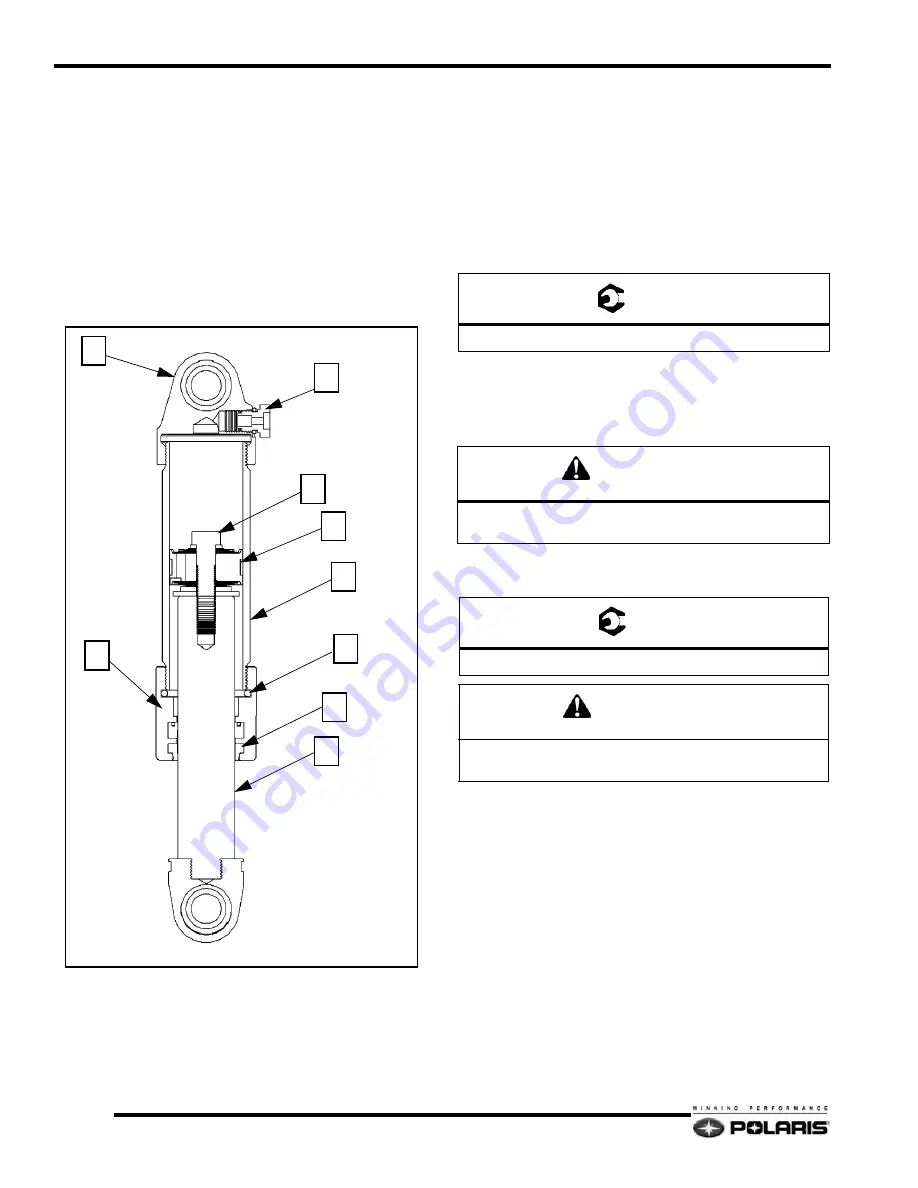
Walker Evans Air Shock Disassembly
IMPORTANT: Verify the protective outer boot is not
torn or damaged. If damaged, inspect the shock shaft
for damage. Replace shock shaft if damage is found.
1.
Place the body cap (1) of the shock in the vise so that the
shock rod (2) is facing downward.
2.
Remove the service port screw (3) and release the pressure
with the shock charging needle. Verify all pressure is
released.
3.
Place the body cap (1) in the vise, so that the shock rod (2)
is facing upward.
4.
Slowly loosen the shock rod bearing cap (4) and remove
from the shock.
5.
Empty all the shock oil from the shock body and discard
the old oil.
6.
Inspect the valve stack (5) as needed. Replace any worn,
wavy, bent valve shims.
7.
If valve shim service or adjustment is done, torque the
piston retaining bolt (6) to 25-30 ft-lb (34-41 N-m).
8.
If required, replace the bearing cap seal (7) and o-ring (8).
Walker Evans Air Shock Assembly
1.
Place the specified amount of fluid into the shock body.
2.
Insert and torque down the bearing cap (4) assembly into
the shock body (9).
3.
Flip shock over in the vise so that the shock rod is facing
downward.
4.
Pressurize the shock to specification. Hold the fill tool
needle in the port for thirty seconds to allow the nitrogen
gas to stabilize.
IMPORTANT: Never re-insert the fill tool needle back
into the shock to check pressure after initial charging.
The amount of gas required to fill the tool will give a
false pressure reading.
Always completely discharge the shock and refill to
obtain an accurate pressure reading.
5.
Check for any leaks.
6.
Reinstall the protective boot and carefully reinstall shock.
3
1
6
7
2
9
4
5
8
=
T
Piston Retaining Bolt: 25-30 ft-lb (34-41 Nm)
CAUTION
Do not overfill the shock oil level. Too much shock oil
may cause the shock rod to hydro lock.
=
T
Bearing Cap Torque: 85 ft-lb (115 N-m)
CAUTION
Do not over-torque the shock rod bearing cap or shock
performance will be compromised.
Summary of Contents for FST IQ 2007
Page 45: ...NOTES Model Specifications 1 42 ...
Page 57: ...NOTES General Information 2 12 ...
Page 79: ...NOTES Maintenance 3 22 ...
Page 84: ...4 5 Fuel Systems 4 Carbureted Fuel System Typical ...
Page 88: ...4 9 Fuel Systems 4 Throttle Opening Vs Fuel Flow VM only ...
Page 101: ...4 22 Fuel Systems Chassis Relay ...
Page 103: ...4 24 Fuel Systems Vehicle Speed Sensor ...
Page 119: ...NOTES Fuel Systems 4 40 ...
Page 183: ...NOTES Final Drive and Brakes 6 16 ...
Page 203: ...NOTES PVT System 7 20 ...
Page 297: ...11 12 Battery and Electrical Systems System Schematic CFI ...
Page 305: ...NOTES Battery and Electrical Systems 11 20 ...
Page 310: ...12 1 Wiring Diagrams 2007 600 HO Carbureted 1 of 2 ...
Page 311: ...12 2 Wiring Diagrams 2007 600 HO Carbureted 2 of 2 ...
Page 312: ...12 3 Wiring Diagrams 2007 600 HO Carbureted Hood Harness ...
Page 313: ...12 4 Wiring Diagrams 2007 600 700 CFI Chassis Harness 1 of 2 ...
Page 314: ...12 5 Wiring Diagrams 2007 600 700 CFI Chassis Harness 2 of 2 ...
Page 316: ...12 7 Wiring Diagrams 2007 600 700 CFI Engine Harness ...
Page 317: ...12 8 Wiring Diagrams 2008 IQ Shift 1 of 2 ...
Page 318: ...12 9 Wiring Diagrams 2008 IQ Shift 2 of 2 ...
Page 319: ...12 10 Wiring Diagrams 2008 IQ Shift Hood Harness ...
Page 320: ...12 11 Wiring Diagrams 2008 IQ Shift RMK 1 of 2 ...
Page 321: ...12 12 Wiring Diagrams 2008 IQ Shift RMK 2 of 2 ...
Page 322: ...12 13 Wiring Diagrams 2008 IQ Shift RMK Hood Harness ...
Page 323: ...12 14 Wiring Diagrams 2008 IQ CFI Chassis Harness 1 of 2 ...
Page 324: ...12 15 Wiring Diagrams 2008 IQ CFI Chassis Harness 2 of 2 ...
Page 325: ...12 16 Wiring Diagrams 2008 IQ CFI Engine Harness ...


