background image

FUEL SYSTEM/CARBURETION

3.3

PILOT JET

From idling to low speeds, the fuel supply is metered by the
pilot jet.  There are several air bleed openings in the sides
of the pilot jet which reduce the fuel to mist.  The number
stamped on the jet is an indication of the amount of fuel in
cc’s which passes through the jet during a one minute inter-
val under a given set of conditions.

PILOT AIR SCREW

The pilot air screw controls the fuel mixture from idle to low
speeds.  The tapered tip of the air screw projects into the air
passage leading to the pilot jet air bleeds.  By turning the
screw in or out, the cross sectional area of the air passage
is varied, in turn varying the pilot jet air supply and changing
the mixture ratio.

AIR/FUEL MIXTURE RATIO

A carburetor with a piston type throttle valve is also called
a variable venturi type carburetor.  In this type of carburetor,
the needle jet and jet needle serve to control a proper air/
fuel mixture ratio at the medium throttle valve opening (be-
tween 1/4 and 3/4 opening).  Having the proper needle jet
and jet needle has a major impact on engine performance
at partial load.

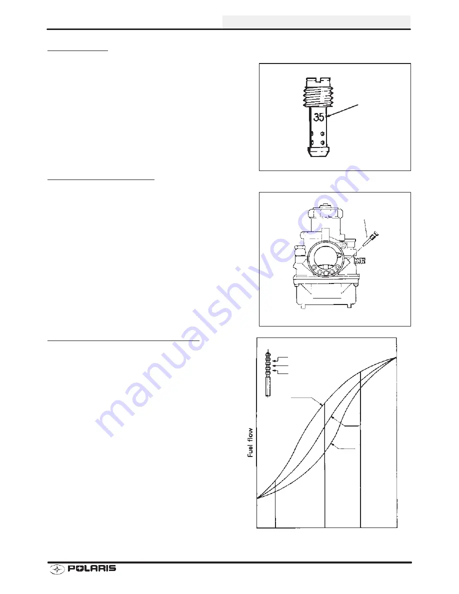
The jet needle tapers off at one end and the clearance be-
tween the jet needle and the needle jet increases as the
throttle valve opening gets wider.  The air/fuel mixture ratio
is controlled by the height of the “E” ring inserted into one
of the five slots provided in the head of the jet needle.  The
chart at right shows the variation of fuel flow based on the
height of the “E” ring.

Pilot Jet
Indicator
Number

Pilot Air Screw

2

3

4

4

3

2

15

50

75

100%

Throttle Valve Opening

E-Clip Position Vs. Fuel Flow

Summary of Contents for 2001 50 SCRAMBLER

Page 1: ...valent Chart 1 7 Unit of Measure Conversion Table 1 8 Tap Drill Charts 1 9 Glossary of Terms 1 10 1 11 Inspection Schedule 1 12 Vehicle Inspection 1 13 1 15 Transmission Lubrication 1 16 Throttle Oper...

Page 2: ......

Page 3: ...Identifier Powertrain Engine Emissions Model Year Plant No Individual Serial No Body Style Check Digit World Mfg ID This could be either a number or a letter ENGINE SERIAL NUMBER LOCATION Whenever cor...

Page 4: ...tomatic C V T System FRONT SUSPENSION A arm with 2 5 cm Travel A arm with 2 5 cm Travel A arm with 2 5 cm Travel REAR SUSPENSION Single Shock Swing Arm with 2 5 cm Travel Single Shock Swing Arm with 2...

Page 5: ...ambler 90 A01EA09CA 9916424 9916432 9916433 9916576 When ordering service parts be sure to use the correct parts manual PAINT CODES PAINTED PART COLOR DESCRIPTION DITZLER NUMBER POLARIS NUMBER 2001 Sc...

Page 6: ...ICANT AND MAINTENANCE PROD UCT PART NUMBERS Part No Description Engine Lubricant 2870791 Fogging Oil 2871098 Premium 2 Cycle Engine Oil Quart 2871097 Premium 2 Cycle Engine Oil Gallon 2871240 Premium...

Page 7: ...Newton Meter to Pound Foot and Pound Inch GENERAL INFORMATION 1 5 TORQUE CONVERSIONS...

Page 8: ...Newton Meter to Pound Foot and Pound Inch GENERAL INFORMATION 1 6 TORQUE CONVERSIONS...

Page 9: ...6 10 mm 3937 13 32 4063 27 64 4219 11 mm 4331 7 16 4375 29 64 4531 15 32 4688 12 mm 4724 31 64 4844 1 2 5 13 mm 5118 33 64 5156 17 32 5313 35 64 5469 14 mm 5512 9 16 5625 37 64 5781 15 mm 5906 19 32 5...

Page 10: ...ubic centimeters cc x 0 061 Cubic inches cu in Imperial pints Imp pt x 0 568 Liters l Liters l x 1 76 Imperial pints Imp pt Imperial quarts Imp qt x 1 137 Liters l Liters l x 0 88 Imperial quarts Imp...

Page 11: ...4 1 1 8 12 1 3 64 1 1 4 7 1 7 64 1 1 4 12 1 11 64 1 1 2 6 1 11 32 1 1 2 12 1 27 64 1 3 4 5 1 9 16 1 3 4 12 1 43 64 2 4 1 2 1 25 32 2 12 1 59 64 2 1 4 4 1 2 2 1 32 2 1 2 4 2 1 4 2 3 4 4 2 1 2 3 4 2 3 4...

Page 12: ...ndicator while crankshaft is supported between centers on V blocks or resting in crankcase Measure at various points especially at PTO DCV Direct current voltage Dial Bore Gauge A cylinder measuring i...

Page 13: ...ne RPM increases Reservoir Tank The fill tank in the liquid cooling system Resistance In the mechanical sense friction or load In the electrical sense ohms Both result in energy conversion to heat Rig...

Page 14: ...ilter I Fuel Oil Lines I Battery I I Brake Shoes I Spark Plug I Chain Lubrication I Steering Lubrication I Carburetor C Throttle Control I Tire Pressure I Fasteners T Gear Oil R R R Replace C Clean T...

Page 15: ...brake setting is achieved Tighten nuts Rear Brake 3 The rear brake is operated using the left hand brake lever To adjust the rear brake setting turn the rear brake adjuster nut until brake is set to...

Page 16: ...lock nut to specification 3 Tighten the four bearing housing bolts to specification Re install rear cover Lubrication 4 Lubricate grease fittings on spindles monthly with Polaris All Season Grease or...

Page 17: ...sman 90 by turning the adjuster nut Inspect the A arm and weldments for any sign damage Rear Shock and Spring 2 Inspect the rear shock and spring to ensure proper function If the shock is leaking oil...

Page 18: ...nge Operating range is 1 2 12 7 mm below the tip of the dipstick To change lubricant 1 Place a drain pan beneath the transmission oil drain plug area 2 Remove the drain plug and wipe the magnetic end...

Page 19: ...if worn kinked or damaged AIR SCREW ADJUSTMENT 1 Turn carburetor air screw in clockwise until lightly seated Back screw out the specified number of turns 2 Warm up the engine to operating temperature...

Page 20: ...throttle cable adjuster and jam nut 2 Set parking brake 3 Start engine and set idle to specified RPM NOTE Be sure the engine is at operating temperature See Idle Speed Adjustment 4 Loosen lock nut on...

Page 21: ...ustment and re adjust if neces sary 8 Turn handlebars from left to right through the entire turning range If idle speed increases check for proper cable routing If cable is routed properly and in good...

Page 22: ...moved from oil pump cable the point where the oil pump arm is just starting to move off of its stop NOTE The pump stop keeps the pump arm from rotat ing any farther down than the idle position so no v...

Page 23: ...rom the intake manifold 3 Test the oil delivery check valve with a low pressure pump and gauge 4 Start engine and lift oil pump lever to full open position 5 Oil should pulse from the delivery line ev...

Page 24: ...wl when the engine is hot Severe burns may result FUEL LINES 1 Check fuel lines for signs of wear deterioration damage or leakage Replace if necessary 2 Be sure fuel lines are routed properly and secu...

Page 25: ...located on the side of the float bowl 1 Turn fuel valve to the off position 2 Place a clean container beneath the bowl drain spigot or bowl drain hose 3 Loosen drain screw and allow fuel in the float...

Page 26: ...ately 3 5 revolutions AIR FILTER SERVICE 1 Remove three 3 screws on the airbox Slide car buretor boot clamp off of carburetor 2 Remove the airbox cover to expose the filter ele ment 3 Carefully wash t...

Page 27: ...ightly 3 Elevate the side of the vehicle by placing a suitable stand under the footrest frame 4 Remove the wheel nuts and remove the wheel WHEEL INSTALLATION 1 With the transmission in gear and the pa...

Page 28: ...fect ATV handling Tire Tread Depth Always replace tires when tread depth is worn to 1 8 3 mm or less WARNING Operating an ATV with worn tires will increase the possibility of the vehicle skidding easi...

Page 29: ...ront and rear of rim NOTE String should just touch side surface of rear tire on each side of machine NOTE The steering post arm frog can be used as an indicator of whether the handle bars are straight...

Page 30: ...erance is 1 8 to 1 4 3 to 6 cm toe out This means the measurement at the front of the tire A is 1 8 to 1 4 3 to 6 cm wider than the measurement at the rear B TOE ALIGNMENT ADJUSTMENT 1 If toe alignmen...

Page 31: ...ecial Tools Engine 2 1 Engine Installation Notes 2 2 Engine Disassembly 2 3 2 12 Engine Inspection 2 13 2 15 Cylinder Honing 2 16 Crankshaft Runout Inspection 2 17 Engine Assembly 2 18 2 16 Spark Plug...

Page 32: ......

Page 33: ...ransmission Cover Bolts 84 in lbs 9 5 Nm Flywheel 25 ft lbs 34 Nm Oil Drain Bolt Transmission 14 ft lbs 19 Nm Oil Pump Bolts 43 in lbs 5 Nm Fan Housing 84 in lbs 9 5 Nm Fan Bolts 84 in lbs 9 5 Nm Stat...

Page 34: ...ly pre ride inspection checklist Exhaust 1 Replace exhaust gaskets Seal connections with high temp silicone sealant 2 Check to be sure all springs are in good condition Engine Break In Period Engine B...

Page 35: ...ENGINE DISASSEMBLY Fan Cover and Cylinder Air Shroud 1 Remove the fasteners on fan cover 2 Remove cylinder air shroud and deflector 3 Loosen bolts securing fan and remove fan Starter Motor 4 Remove st...

Page 36: ...nifold Remove intake manifold and reed valve NOTE Remove any remaining gasket material from the reed valve housing and crankcase Always replace the reed valve gasket when removing NOTE Check the condi...

Page 37: ...Always replace head gasket with new 10 Remove cylinder Clean the carbon from the cylinder walls and ports using parts washer solvent Inspect the cylinder walls for signs of scoring Piston Pin Piston a...

Page 38: ...rings so no damage is done to the ring lands Discard rings and replace with new 14 Remove small end bearing from connecting rod Transmission System 15 Loosen and remove all bolts protectors carburetor...

Page 39: ...r bolts grommets protectors filter and remove carburetor tube bracket and crankcase cover Sportsman 90 and Scrambler 90 Remove gasket and discard 17 Remove drive clutch nut 18 Remove one way clutch wa...

Page 40: ...lt 21 Remove primary clutch sheave 22 Remove the nut on driven clutch and remove clutch assembly NOTE Be careful not to lose the oil ring upon removal Starter Clutch Set 23 Remove idle gear bolts 24 R...

Page 41: ...5 Remove the starter clutch starter gear needle bearing and washer Driven Shaft Assembly 26 Drain the oil from gear case 27 Remove transmission cover and gasket 28 Remove the driven clutch shaft compo...

Page 42: ...bly 29 Remove flywheel nut and washer 30 Remove the flywheel using flywheel puller 31 Scribe an alignment mark on the stator backing plate and the crankcase for proper alignment upon engine assembly R...

Page 43: ...ve stator gasket clean the area thoroughly Loosen bolts and remove the oil pump 33 Remove external circlips and use a special tool to remove the oil pump drive gear 34 Loosen the bolts and remove the...

Page 44: ...Use a special tool to disassemble the right and left crankcase halves 36 Use a special tool to remove the crankshaft 37 Remove the external snap ring on the output shaft bearing and remove the oil se...

Page 45: ...ment is needed 3 Inspect the cylinder walls for damage or scoring The cylinder bore must be de glazed whenever new piston rings are installed If cylinder wear or damage is excessive it will be necessa...

Page 46: ...e surface of the piston pin for damage Measure the diameter of the piston pin in three areas with a micrometer The service limit for the piston pin is 393 9 980 mm Connecting Rod Inspection 4 Inspect...

Page 47: ...xceeds the limit replace the clutch cover Compression Spring 3 Use a vernier caliper to inspect the length of the compression spring With the spring at full extension the measurement should be no less...

Page 48: ...ttern to ensure piston ring seating and to aid in the retention of the fuel oil mixture during initial break in Hone cylinder according to hone manufacturer s instructions or these guidelines S Use a...

Page 49: ...urely in the holding fixture Refer to the illustrations below 1 If the runout of the crankshaft is more than 004 100mm on the MAG side or 006 150mm on the PTO side the crankshaft must be replaced Cran...

Page 50: ...in one of the crankcase halves Install a new crankcase gasket and install the other side of the crankcase Torque the crankcase bolts to specification 3 Install the oil pump bracket inside the MAG side...

Page 51: ...sket 6 Install stator Torque bolts to specification 7 Inspect flywheel key for damage Replace if necessary Install flywheel and torque to specification 8 Install driven clutch shaft components and sha...

Page 52: ...for leaks 11 Install the starter clutch starter gear needle bearing and washer 12 Install the plate shaft pin washers and idler gear 13 Install idle gear bolts and torque to specification Transmissio...

Page 53: ...oil ring driven clutch and driven clutch nut on output shaft Torque nut to specification 15 Install primary clutch sheave 16 Install drive belt 17 Install the primary fixed sheave and claw washer Dri...

Page 54: ...t and crankcase cover Sportsman 90 and Scrambler 90 Torque cover bolts to specification 20 Install new gasket bolts grommets protectors filter and install carburetor tube bracket and cover Scrambler 5...

Page 55: ...nd bearing into connecting rod 22 Carefully install new piston rings so no damage is done to the piston or ring lands 23 Install new base gasket and carefully install new piston and piston pin Use car...

Page 56: ...park plug Spark plug gap should be 024 028 6 7 mm 28 Install intake manifold and reed valve Install bolts securing the intake manifold Torque to specification NOTE Remove any remaining gasket material...

Page 57: ...crew to specification 30 Install air duct to carburetor 31 Install starter motor Torque bolts to specification 32 Install fan Torque fan bolts to specification Carburetor Adaptor Screw Torque 20 in lb...

Page 58: ...GINE 2 26 ENGINE ASSEMBLY 33 Install cylinder air shroud and deflector 34 Install fasteners on fan cover and torque bolts to specification Cylinder Air Shroud and Deflector Screw Torque 84 in lbs 9 5...

Page 59: ...le jet locating pins S Loose jets in carburetor or calibration incorrect for altitude temperature S Incorrect float level setting S PVT system calibrated incorrectly or components worn or mis adjusted...

Page 60: ...uretor pilot system S Carburetor misadjusted S Choke not adjusted properly S Low compression S Crankcase breather restricted Engine Idles But Will Not Rev Up S Spark plug fouled weak spark S Broken th...

Page 61: ...g S Fouled spark plug or incorrect plug or plug gap S Carburetion faulty lean condition S Exhaust system air leaks S Ignition system faulty Spark plug cap cracked broken Ignition coil faulty Ignition...

Page 62: ......

Page 63: ...dle Jet Throttle Opening 3 4 Throttle Valve Main Jet 3 5 Pilot System 3 6 Slide Cutaway 1 8 3 8 Throttle 3 7 Jet Needle Needle Jet 3 8 3 4 Throttle 3 8 Main System 3 4 to Full Throttle 3 9 Fuel Delive...

Page 64: ......

Page 65: ...stored Do not overfill the tank Do not fill the tank neck If you get gasoline in your eyes or if you swallow gasoline see your doctor immediately If you spill gasoline on your skin or clothing immedi...

Page 66: ...has varying operations depend ing upon varying driving conditions It is constructed of a float system pilot system main system and starter system or initial starting de vice FLOAT SYSTEM The float sys...

Page 67: ...xture ratio AIR FUEL MIXTURE RATIO A carburetor with a piston type throttle valve is also called a variable venturi type carburetor In this type of carburetor the needle jet and jet needle serve to co...

Page 68: ...her pro duces a leaner mixture If the taper is worn due to vibration fuel flow may be significantly affected NEEDLE JET The needle jet works in conjunction with the jet needle to regulate fuel flow ra...

Page 69: ...f the cutaway The higher the number the leaner the gasoline air mixture MAIN JET When the throttle opening becomes greater and the area between the needle jet and jet needle increases fuel flow is met...

Page 70: ...pilot jet is drawn from the float bowl mixed with air regulated by the air screw and delivered to the engine through the pilot outlet The mixture is regulated to some degree by adjusting the air screw...

Page 71: ...s less resistance to air flow A flat angle would provide a much richer mixture because there is more resistance to air flow The venturi shape can be adjusted for each engine s breathing characteristic...

Page 72: ...dle Moving the clip down raises the needle in the jet passage and richens the mixture Moving the clip up lowers the needle in the jet passage and leans the mixture Letter and number codes are stamped...

Page 73: ...ed driving there is very little clearance between the jet needle and the needle jet therefore very little fuel from the main jet can pass between the jet needle and the needle jet As the throttle valv...

Page 74: ...ottle and consistently increases to full throttle opening Carburetor Component Function 2 Cycle System Main Components Main Function Main Affect Float System Fuel Level Control Inlet Pipe Needle and S...

Page 75: ...ve pin without compressing the spring 3 Measure height from float bowl mating surface to float arm as shown Both sides of float arm must be parallel to each other Use float adjustment tool PN 2872314...

Page 76: ...s located on the side of the float bowl 1 Turn fuel valve to the off position 2 Place a clean container beneath the bowl drain spigot or bowl drain hose 3 Loosen drain plug and allow fuel in the float...

Page 77: ...Drain Plug 15 Bolt 16 Washer 17 Bolt 18 Starter Plunger 19 O ring 20 Throttle Screw 21 Needle and Seat 22 Float Pin 23 Cable Adjuster Nut Carburetor Exploded View 1 2 3 4 5 Jet Needle E Clip Position...

Page 78: ...S Incorrect pilot screw adjustment RICH MIXTURE Symptoms Fouls spark plugs black sooty exhaust smoke rough idle poor fuel economy engine runs rough misses poor performance bog engine loads up backfir...

Page 79: ...orn jet needle needle jet ERRATIC IDLE S Choke cable bending or incorrectly adjusted S Throttle cable incorrectly adjusted S Air leaks dirty carburetor passages pilot circuit S Pilot mixture screw dam...

Page 80: ......

Page 81: ...d Special Tools 4 1 Frame Photos 4 2 Engine Mounting 4 3 4 4 Shocks and Springs 4 5 Suspension A arms 4 6 Steering 4 7 4 8 Front Brake 4 9 4 10 Rear Brake and Axle 4 10 4 13 Fuel and Oil Tank 4 14 Fro...

Page 82: ......

Page 83: ...ndle Nuts 40 45 ft lbs 58 62 Nm Steering Post Mount Nuts 103 in lbs 11 6 Nm Steering Post Nut 62 65 ft lbs 86 90 Nm Steering Nuts 62 65 ft lbs 86 90 Nm Sprocket Bolts 18 ft lbs 25 Nm Chain Tensioner B...

Page 84: ...BODY STEERING SUSPENSION 4 2 FRAME PHOTOS Side View Front View Rear View...

Page 85: ...BODY STEERING SUSPENSION 4 3 ENGINE MOUNTING Rubber Bushings Mount Tube Engine Bracket Rubber Bushing...

Page 86: ...e three 3 engine mounting positions on the frame Check each bushing of the engine brackets for damage or wear before mounting the engine to the frame body 4 Insert the engine into the frame body Mount...

Page 87: ...front springs on the Sportsman 90 can be adjusted for more or less spring preload depending on rider preference 2 The rear shock and spring is mounted to the frame and swing arm The rear spring can be...

Page 88: ...2 Grease spindles and mount the spindles on the A arms The spindle marked R is for right side and L for left side Torque the spindle nut to specification Insert cotter key A arm Bolts A arm Mounting B...

Page 89: ...steering post clamps on post Install the steering post and tighten the steering post mount nuts to specification Steering Post Mount Nut Torque 103 in lbs 11 6 Nm Steering Post Steering Post Bushings...

Page 90: ...ng 3 Mount the tie rod to the steering post and to the spindle Mount the tie rod so that the end with the flats is toward the spindle 4 Tighten inner and outer tie rod bolts to specification Steering...

Page 91: ...the front brake drums Upon disassembly inspect the bearings and seals for damage Replace bearings and seals if necessary Brake Arm Brake Cam Shaft Return Spring Brake Plate Brake Shoe Brake Drum Right...

Page 92: ...d tighten the spindle nut to specification 5 Connect the brake cable with brake arm 6 Install the rubber cap REAR BRAKE AND AXLE Spindle Nut Torque 42 45 ft lbs 58 62 Nm Rear Brake Cable Rear Brake Dr...

Page 93: ...stall rear shock and spring Tighten shock mounting bolts to specification 3 Inspect the protective rubber gasket on the rear brake drum for damage Replace if needed Mount the rear brake plate shoes an...

Page 94: ...carrier needs to be adjusted for chain tension Do not tighten to specified torque at this time 6 Install the drive sprocket on the rear wheel axle 7 Install the right and left spacer tube on the rear...

Page 95: ...djuster Turn the adjuster until the chain tension is set Tighten the adjuster nuts 12 Tighten all bearing carrier bolts to specification 13 Install the rear cover Torque bolts to specification Sprocke...

Page 96: ...good condition 2 Install the oil tank to the frame and tighten bolts to specification Always fill the oil reservoir before riding 3 The fuel petcock has ON OFF and RES Make note of these positions on...

Page 97: ...e front and rear cab to the frame The front cab is mounted on positions 1 and 2 The rear cab is mounted on position 3 3 Install the front and rear cab to the frame and tighten the mounting bolts to sp...

Page 98: ...the engine stop switch and start switch There is a parking brake on the left brake lever It is designed for safety assurance Always engage the parking brake when the vehicle is stopped and the engine...

Page 99: ...ottle ETC switch box and lightly grease the throttle cable A Install the throttle able Handlebar Mounting Clamp Bolt Torque 84 in lbs 10 Nm Front Brake Lever Free Play 40 80I 10 20 mm Front Brake Leve...

Page 100: ...cover MUFFLER 1 Connect the muffler to the cylinder and install Inspect sealing gaskets upon installation Replace if necessary 2 Connect the muffler to the mounting bracket on the frame Tighten bolt...

Page 101: ...ent Draw Key Off 5 6 Charging System Testing 5 7 Ignition System 5 8 5 9 Cranking Output Test 5 10 CDI Output Test 5 10 Charging System Testing 5 11 5 12 Alternator Output Test AC Amp 5 13 Starter Sys...

Page 102: ......

Page 103: ...for current readings Refer to the Owner s manual included with your meter for more information SVoltage amperage and resistance values included in this manual are obtained with a Fluke 73 Digital Mult...

Page 104: ...battery perform the following steps NOTE Do not service the battery unless it will be put into regular service within 30 days After initial service add only distilled water to the battery Never add el...

Page 105: ...of one cup water and one tablespoon baking soda Rinse with clean water and dry thoroughly 2 Reinstall battery attaching positive red cable first and then the negative black cable Coat terminals and b...

Page 106: ...less than 1 115 At 80_F NOTE Subtract 01 from the specific gravity reading at 40_ F LOAD TEST CAUTION Remove spark plug high tension leads and connect securely to engine ground before proceeding NOTE...

Page 107: ...ry dis charges The chart at right indicates freezing points by specific gravity CHARGING PROCEDURE Charge the battery with a charger no larger than 1 10 of the battery s amp hr rating for as many hour...

Page 108: ...in series with the negative battery cable Check for current draw with the key off If the draw is excessive loads should be disconnected from the system one by one until the draw is eliminated Check c...

Page 109: ...ctions SWith engine off and the key and kill switch in the ON position the ammeter should read negative amps battery discharge Reverse meter leads if a positive reading is indicated SElevate machine s...

Page 110: ...the resistance reads replace coil 2 Measure the resistance between the spark plug cap and coil Resistance should read 8 0 9 3 K with cap installed 3 Remove the spark plug cap and measure resistance ag...

Page 111: ...or moisture wire color matching or corrosion Yes No Yes Check coil ground connection between engine and coil mount using an ohmmeter The coil mount should have good continuity to ground on the engine...

Page 112: ...tor connectors from the CDI module Test output from exciter coil pulse trigger coil and compare to the chart The following measurements are obtained when cranking the engine with the electric start er...

Page 113: ...ery voltage must be present on red wire terminal on harness side of voltage regulator connector Is it Check regulator rectifier connections and ground battery connections cir cuit breaker and connecti...

Page 114: ...an ammeter set to DC amps in series be tween the negative battery cable and terminal SConnect a tachometer according to manufacturer s in structions SWith engine off and the key and kill switch in the...

Page 115: ...eter leads to the Yellow and Yellow Red wires leading from the alternator SStart the engine and let it idle Reading should be a minimum of 5A at idle CAUTION This test simulates a full load on the alt...

Page 116: ...roblem seized or binding Can engine be rotated easily with recoil starter SFaulty or worn brushes in starter motor SAutomatic compression release inoperative Starter Motor Turns Engine Does Not Rotate...

Page 117: ...connect the solenoid Connect the tester black lead to the battery positive and the red lead to the solenoid end of the battery to solenoid wire De press starter button Reading should be less than 1 V...

Page 118: ...a residue or damage inter nal parts and insulation 1 Note the alignment marks on both ends of the starter motor casing These marks must align during reassembly 2 Remove the two bolts washers and seali...

Page 119: ...r large phenolic washer two small phenolic washers and O Ring from brush terminal Inspect the O Ring and replace if damaged 3 Remove brush plate and brushes Measure length of brushes and replace if wo...

Page 120: ...tator Replace if excessively worn or damaged 3 Using a digital multitester measure the resistance between each of the commutator segments The reading should be 3 ohms or less 4 Measure the resistance...

Page 121: ...e and install housing aligning marks 5 Install O Ring on other end of field magnet casing Make sure it is in good condition and not twisted on the case 6 Align casing marks and install housing pushing...

Page 122: ...imit Test the ETC switch at the harness connector NOTE Adjust throttle cable freeplay ETC switch and make sure throttlemechanismisfunctioningproperlybeforetestingtheswitch RefertoMaintenanceChapter2fo...

Page 123: ...misadjusted or faulty STerminal board or connections wet corroded SPoor ignition coil ground e g coil mount loose or corroded SFaulty stator measure resistance of all ignition related windings SIncor...

Page 124: ...ELECTRICAL 5 22 WIRING DIAGRAM 2001 SCRAMBLER 50...

Page 125: ...ELECTRICAL 5 23 WIRING DIAGRAM 2001 SCRAMBLER 90 SPORTSMAN 90 2002 SPORTSMAN 90 2002 SCRAMBLER 90...

Reviews: