Pa
ge
17
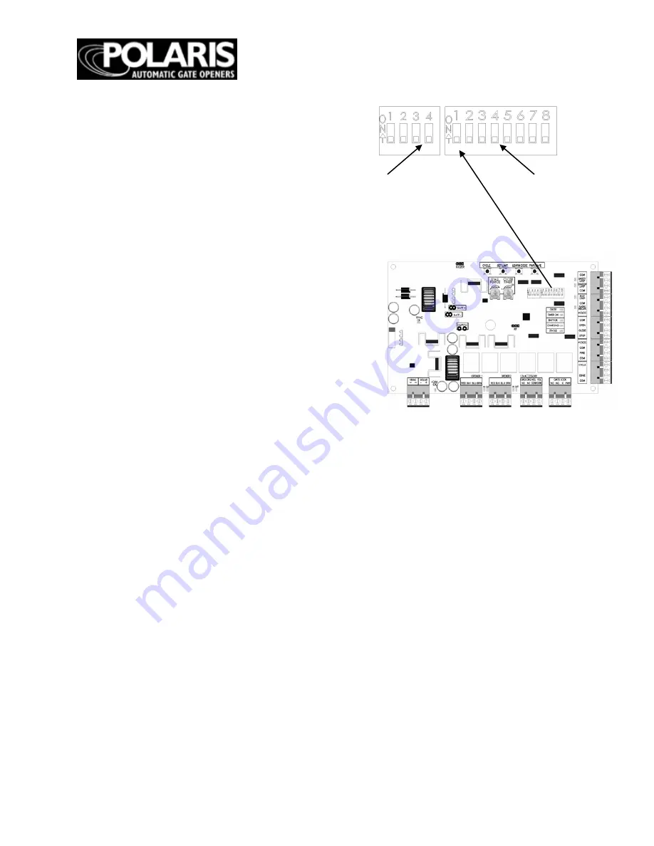
DIP SWITCHES
* - Default factory setting
Block 1, DIP Switch 1 – Auto Close
ON – Auto close feature enabled
OFF* – Auto close feature disable
Block 2, DIP Switch 2 – Pull-to-Open or Push-to-
Open for Primary Gate Operator
ON – Primary gate operator set up for push-to-open
operation
OFF* – Primary gate operator set up for pull-to-open
operation
Block 2, DIP Switch 3 – Pull-to-Open or Push-to-
Open for Secondary Gate Operator
ON – Secondary gate operator set up for push-to-
open operation
OFF* – Secondary gate operator set up for pull-to-
open operation
NOTE: Only active if Block 2, DIP Switch 1 is set in
the ON position
Block 2, DIP Switch 4 – Timing of Dual Gates
ON – One gate is delayed when opening or closing
OFF* – Gates open and close simultaneously
NOTE: Only active if Block 2, DIP Switch 1 is set in
the ON position
ON – Extended soft start/stop operation enabled
OFF* – Normal soft start/stop operation
Block 1, DIP Switch 4 – Time of Soft Start/Stop
ON – Max. extended time of soft start/stop operation
OFF* – Extended time of soft start/stop operation
NOTE: Only active if Block 1, DIP 3 is set to ON
Block 2, DIP Switch 1 – Single or Dual Gate
ON – Dual gate applications
OFF* – Single gate applications
Block 1, DIP Switch 2 – Audible Motion Alarm
ON – Audible motion alarm enabled
OFF* – Audible motion alarm disabled
Block 1, DIP Switch 3 – Extended Soft Start/Stop
NOTE: To adjust auto close time refer to figure 17.
Block 2
Block 1
NOTE: All DIP
Switches are
shown in the factory
Block 2, DIP Switch 5 – Sequencing of
Dual Gate
Opening and Closing
ON – Secondary gate operator opens
first and closes
second (2 second delay)
OFF* – Primary gate operator opens
first and closes
second (2 second delay)
NOTE: Only active if Block 2, DIP 4 is
in the ON position
Block 2, DIP Switch 6 – Dual Gate
Position Limit
Settings
ON – Set limit setting for secondary
gate operator
OFF* – Set limit setting for primary
gate operator
NOTE: Only active if Block 2, DIP
Switch 1 is set in the
ON position
Block 2, DIP Switch 7 – Off - Not Used
Block 2, DIP Switch 8 – Off - Not Used
Summary of Contents for 502
Page 9: ...Page 9 ...
Page 10: ...Page 10 ...
Page 11: ...Page 11 Bushings to be set between bottom side of actuator rod ends and mounting bracket ...
Page 12: ...Page 12 ...
Page 21: ...Page 21 WIRING THE OPERATOR ...
Page 33: ...Page 33 EXIT WAND HOOK UP DIAGRAM ...


