INSTRUCTION MANUAL
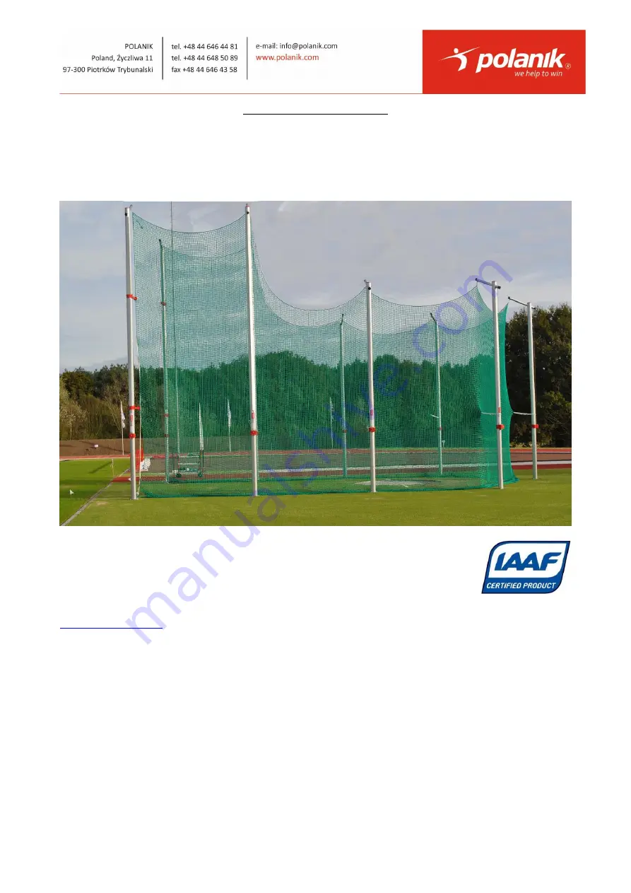
Safety cage for discus throw
KLD17-5/7-A
File: 2018-03-09 PRODUCT SUPPORT Pawel Ciechanowski
[email protected]
Page 1: ...INSTRUCTION MANUAL Safety cage for discus throw KLD17 5 7 A File 2018 03 09 PRODUCT SUPPORT Pawel Ciechanowski p ciechanowski polanik com ...
Page 2: ...original cost of the product Specific warranty terms 1 The use of the throwing cage KLD17 5 7 A is to be done in the properly marked and secured sports facility designed for that purpose and under supervision of qualified coaches and according to the rules of the International Association of Athletics Federations IAAF respective national athletics federation and local safety regulations Failure to...
Page 3: ...ttom by means of steel cable and hooks That lets us eliminate traditional bags filled with send 4 Easy operating Cage can be assembled and disassembled without using a crane or an extension arm Assembly or disassembly takes approximately 3 hours done by 3 4 people Each pillar is equipped with the self blocking mechanism of lifting and lowering the net by means of crank We deliver the cage to a cus...
Page 4: ...raw no Part set sketch 1 Rear pillar length approx 5 m 5 Anodized aluminium and electro galvanized steel 1 2 Central pillar length approx 7 m 2 Anodized aluminium and electro galvanized steel 2 3 Extreme pillar length approx 7 m with guide loop installed 2 Anodized aluminium and electro galvanized steel 3 ...
Page 5: ...down and secured with rubber sleeves 2 Electro galvanized steel 3 4 6 Hinge axle 11 x 350 1 Electro galvanized steel 7 Crank 2 Electro galvanized steel 1 2 3 8 Net with rim vertical steel cables 1 polypropylene 9 Bottom net tension steel cable nut M 16 1 pc washer 16 1 pc 1 Electro galvanized steel 10 Net hooks 100 Electro galvanized steel 11 Side arm screw M 8x25 16 pcs nut M 8 16 pcs washer 8 16...
Page 6: ...g no 1 and 2 which are embedded in concrete according to the plan of the foundation blocks drawing no 3 The anchors should be positioned in concrete in such a way that their hinges and arms face the throwing circle Installed pillars constitute the main structure of the cage which is ready for affixing the net and hoisting it Standard anchor item 4 Extreme anchor item 5 Central pillar item 2 Extrem...
Page 7: ...ing to the direction lines on the anchors plates see Draw no 4 p 18 Each anchor must be embedded in the foundation block in such a way that its upper surface is exactly horizontal then the pillar is vertical and flash with the target surface of the throwing facility see Drawings no 1 2 and 3 p 15 and next ATTENTION The anchors should be placed in the concrete of the class B20 C16 20 quality or hig...
Page 8: ...The installation of pillars item 1 2 and 3 on anchors item 4 and 5 is done as follows a unpack delivered pillars b remove blocking screws M 8x16 from the ratchet mechanisms c loosen steel ropes d fasten temporarily steel rope loop to lever of ratchet mechanisms ...
Page 9: ...n upright position the other person is screwing it to the anchor in the following sequence a screw down two screws M 20 x 50 opposite the anchor hinges b then screw down two remaining screws M 20 x 50 next to the anchor hinges c remove hinge axle item 6 Before you install extreme pillars item 3 two side arms item 11 must be installed on each extreme pillar one side arm at the height of 2 5 m and t...
Page 10: ...ends of their hooks directed towards the outside of the cage see the drawing below a side arm item 11 Extreme pillars item 3 are mounted on extreme anchors item 5 in the same way as rear pillars item 1 and central pillars item 2 are installed ...
Page 11: ...lar 7 m item 2 c standard pillar item 4 d bottom net tension steel cable item 9 e extreme anchor item 5 Unscrew the adjusting nut until 1 cm of threads remains Remove the clamp from the other end of the steel rope Thread the rope end through the loops of the embedded anchors starting from the extreme anchor use its lower loop Then reinstall the clamp pull the rope end to tighten it preliminarily ...
Page 12: ...ropes of the pillars by means of special catches One end of each steel rope is fixed permanently to the bobbin of the ratchet mechanism and the other one which has been temporarily fastened to the pillar should be now untied and attached to the net That operation is repeated at each pillar Rear and central pillar rope fastened to cage net Extreme pillar steel rope fastened to cage net After linkin...
Page 13: ... the net and fix its edge to the meshes with supplied net hooks item 10 Now attach vertical steel rope which is woven into the net mesh edge to the upper loop of the extreme anchor Then we lift the net at the extreme pillars item 3 all the way to the maximum height using the crank item 7 Now the side edges with the steel vertical rope of the hoisted net have to be hooked up on the side arms item 1...
Page 14: ...iable in use However the cage like any other pieces of sports equipment requires periodical inspections and must be used according to the instruction manual the IAAF rules and operated by authorized personnel To keep the cage in good condition the following maintenance operations and periodical inspections should be executed after every athletic season Check the tensile strength of the net use the...
Page 15: ...5 m item 1 b hinges of standard anchor item 4 c direction line of anchor positioning d standard anchor top view and vertical section item 4 e top surface flash with anchor top surface f synthetic sports surface optional g sand bed Foundation block of rear pillar Drawing no 1 ...
Page 16: ...b hinges of standard anchor item 4 c direction line of anchor positioning d standard anchor top view and vertical section item 4 e top surface flash with anchor top surface f synthetic sports surface optional g sand bed Foundation block of central pillar Drawing no 2 ...
Page 17: ... b hinges of extreme anchor item 5 c direction line of anchor positioning d extreme anchor top view and vertical section item 5 e top surface flash with anchor top surface f synthetic sports surface optional g sand bed Foundation block of extreme pillar Drawing no 3 ...
Page 18: ...Instruction manual KLD17 5 7 A 18 21 a standard anchor item 4 b projection of net c extreme anchor item 5 Positions of anchor foundation blocks Drawing no 4 ...
Page 19: ...Instruction manual KLD17 5 7 A 19 21 KLD17 5 7 A side view Drawing no 5 ...
Page 20: ...Instruction manual KLD17 5 7 A 20 21 X IAAF Certificate ...
Page 21: ...used as an general illustration of the installation process The enclosed instructional CD can be viewed on VCD DVD players and PC or MAC computers If it does not start automatically please explore CD main directory and click the file with exe extension Minimal hardware requirements PC P166 MMX 32 MB RAM CD ROM VIDEO CARD WINDOWS 9x NT 4 0 2000 WINDOWS MEDIA PLAYER MAC QUICK TIME PLAYER WITH QUICK ...