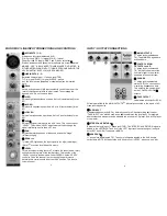
MONO MIC / LINE INPUT CONNECTIONS AND CONTROLS
①
MIC INPUTS (1 - 2)
Microphone input jack (balanced XLR)
PIN 1: ground, PIN 2: (+) signal, PIN 3: (-) signal
P48VDC supply: PINS 2 and 3 (when activated)
η
Ribbon, condenser and dynamic microphones are accommodated.
NEVER
②
LINE INPUTS (1 - 2)
USE A BALANCED-TO-UNBALANCED ADAPTER IN
EITHER MICROPHONE INPUT! THE MICROPHONE AND/OR THE
48V “PHANTOM” SUPPLY MAY BE DAMAGED!
Balanced line level input, ¼” phone jack (TRS)
TIP: (+) signal, RING: (-) signal, SLEEVE: ground
Any line level source (balanced or unbalanced) can be inserted
here.
③
GAIN
Rotary microphone or LINE input sensitivity control. Use to set the
level of this channel relative to other inputs. Thus creating the
desired “mix”. Do not use as a fader.
④
HI EQ
Adjusts high frequencies up or down. Set to 0 (center detent) for no
EQ.
⑤
MID EQ
Adjusts mid frequencies up or down. Set to 0 (center detent) for no
EQ.
⑥
LOW EQ
Adjusts low frequencies up or down. Set to 0 (center detent) for no
EQ.
⑦
AUX
η
Adjusts the signal level sent to the AUX 1
bus.
This control is post
“LEVEL”. This means “LEVEL” adjustments
will also
change the
signal level being sent to the AUX 1 bus.
⑧
PAN
Adjusts the relative position of the sound across the “stage”
(left/center/right).
⑨
PEAK
LED
This red LED lights when the input signal is too high. Lower input
“GAIN”
③
or source level when this occurs.
⑩
LEVEL
This is a compact mixing console. To reduce the console size, rotary
knobs are used in place of the familiar slider. The function of the
“LEVEL” control is the same as a linear FADER. Use the “LEVEL”
control to “fade” the channel in or out during the performance.
Normally this control should be at the 12:00 position, This is not a
volume control.
4
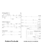
INPUT / OUTPUT CONNECTIONS
Ⓐ
MAIN OUTPUTS
¼” phone jacks (unbalanced
TS). The MAIN MIX signals are
available here.
Ⓑ
CONTROL ROOM
OUTPUTS L
and R
¼” phone jacks (unbalanced
TS). Normally used to provide
line level signal to the monitor
speakers in the control room.
Ⓒ
PHONES
¼” phone jack (unbalanced
stereo TRS). You can connect
monitoring headphones here.
This output is the same signal
as the CONTROL ROOM
Ⓑ
outputs.
Ⓓ
TAPE OUTPUT
Unbalanced phono jacks (RCA).
Wired in parallel with the MAIN OUTPUTS
Ⓐ
. Normally connected to the inputs of a 2-
track recording device.
Ⓔ
TAPE INPUT
Unbalanced phono jacks (RCA). Normally used for a 2-track recording device input.
“TAPE INPUT” can also be used as an additional stereo line level input. For example,
additional sound elements can be added to the mix from a CD player, iPod, MP3 player
or computer.
Ⓕ
STEREO AUX RETURN
η
Balanced line level input, ¼” phone jack (TRS). The “STEREO AUX RETURN” signal is
added to the LEFT/RIGHT bus. If only the LEFT input jack is used the signal is sent to
both LEFT and RIGHT channels. (MONO)
Ⓖ
AUX SEND
η
¼” phone jack (unbalanced TS). The sum of all signals applied to the AUX bus are
output here. NOTE: All feeds to the AUX bus are
POST
-“LEVEL”, also known as “wet”.
9


