PNY MBM630I7150 User Manual Download Page 9

-  -

 nVIDIA MCP73 Series                                                                                     Users Manual

Chapter 2 Hardware Setup

2.1 Choosing a Computer Chassis


• Choose a chassis big enough to install this mainboard.


• As some features for this mainboard are implemented by cabling connectors on the


mainboard to indicators and switches or buttons on the chassis, make sure your chassis 


supports all the features required.


• If there is possibility of adopting some more hard drives, make sure your chassis has 


sufficient power and space for them.


• Most chassis have alternatives for I/O shield located at the rear panel. Make sure the I/O


shield of the chassis matches the I/O port configuration of this mainboard. You can find


an I/O shield specifically designed for this mainboard in its package.

2.2 Installing Mainboard

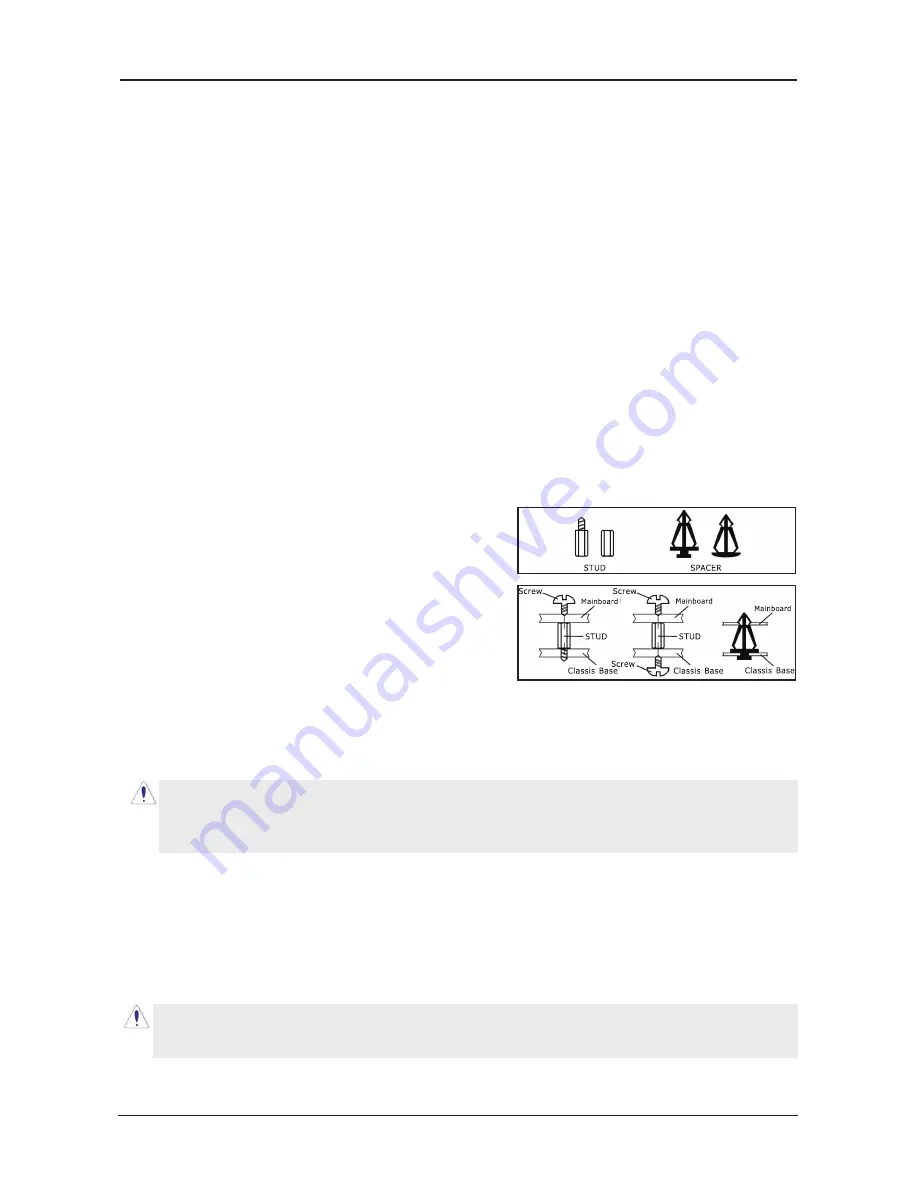
    Most computer chassis have a base with many mounting holes to allow the mainboard to     

    be securely attached, and at the same time, prevent the system from short circuits. There     

    are two ways to attach the mainboard to the 

    chassis base: (1) with studs, or (2) with spacers.

    Basically, the best way to attach the board is with 

    studs. Only if you are unable to do this should you

    attach the board with spacers. Line up the holes on

    the board with the mounting holes on the chassis. 

    If the holes line up and there are screw holes, you

    can attach the board with studs. If the holes line 

    up and there are only slots, you can only attach with

    spacers. Take the tip of the spacers and insert them

    into the slots. After doing this to all the slots, you can slide the board into position aligned 

    with slots. After the board has been positioned, make sure everything is OK before putting 

    the chassis back on.

    To install this mainboard:

    1. Locate all the screw holes on the mainboard and the chassis base.

    2. Place all the studs or spacers needed on the chassis base and have them tightened.

    3. Face the mainboard’s I/O ports toward the chassis’s rear panel.

    4. Line up all the mainboard’s screw holes with those studs or spacers on the chassis.

    5. Install the mainboard with screws and have them tightened.

Always power off the computer and unplug the AC power cord before adding or removing     

any peripheral or component. Failing to do so may cause severe damage to your 

mainboard and/or peripherals. Plug in the AC power cord only after you have carefully 

checked everything.

To prevent shorting the PCB circuit, please REMOVE the metal studs or spacers if they are     

already fastened on the chassis base and are without mounting-holes on the mainboard to     

align with.

Summary of Contents for MBM630I7150

Page 1: ...MBM630I7150...

Page 2: ...not guarantee the accuracy of the contents This manual is purely technical documentation without any hint or other meanings and we won t commit users misunderstanding of the typesetting error Our prod...

Page 3: ...r Connectors 12 3 5 Front Panel Switches Indicators Headers 12 3 6 Additional USB Port Headers 13 3 7 Front Panel Audio Connection Header 13 3 8 Internal Audio Connectors 14 3 9 S PDIF Output Connecti...

Page 4: ...ase check the following packing and accessories if there is any broken or part missing please contact with your franchiser HDD Cable X 1 Serial ATA Cable X 1 Rear I O Panel X 1 User s Manual X 1 Drive...

Page 5: ...CPU temperature Fan speed System Voltage monitoring Integrate Ports 1 X PS 2 Keyboard port 1 X PS 2 Mouse port 1 X VGA port MCP73D not support 1 X DVI port MCP73D V not support 1 X HDMI port MCP73D V...

Page 6: ...nVIDIA MCP73 Series Users Manual 1 3 Mainboard Layout MCP73V 1 0 This picture is only for reference VGA...

Page 7: ...nVIDIA MCP73 Series Users Manual 1 3 Mainboard Layout MCP73PV U This picture is only for reference...

Page 8: ...upport DVI Connect to monitor input MCP73D V not support LAN Connect to Local Area Network USB Connect to USB devices such as scanner digital speakers monitor mouse keyboard hub digital camera joystic...

Page 9: ...acers Line up the holes on the board with the mounting holes on the chassis If the holes line up and there are screw holes you can attach the board with studs If the holes line up and there are only s...

Page 10: ...U graphics card memory hard drive etc 2 3 1 Installation of the CPU 1 Open the socket lever by pushing the lever down and away from the socket see Figure 1 1 and 2 2 Lift the load plate Do not touch t...

Page 11: ...keep away from touching its connectors 4 Align the notch key on the module with the rib on the slot 5 Firmly press the module into the slots until the ejector tabs at both sides of the slot automatic...

Page 12: ...nto slot PCIE2 Install PCI Express X1 card into slot PCIE1 Install PCI card into slots PCI1 or PCI2 Each of the IDE port connects up to two IDE drives at Ultra ATA 66 100 133 mode by one 40 pin 80 con...

Page 13: ...ock was incorrectly set in the BIOS menu or d whenever there is modification on the CPU or memory modules This header uses a jumper cap to clear the CMOS memory and have it reconfigured to the default...

Page 14: ...s connector connects to the case mounted reset switch for rebooting your computer without having to turn off your power switch This is a preferred method of rebooting in order to prolong the lift of t...

Page 15: ...d 8 Ground 10 NC HD Audio Pin No Definition 1 MIC2_L 2 GND 3 MIC2_R 4 ACZ_DET 5 LINE2_R 6 FSENSE1 7 FAUDIO_JD 8 No Pin 9 LINE2_L 10 FSENSE2 AC 97 Audio Pin No Definition 1 MIC 2 GND 3 MIC Power 4 NC 5...

Page 16: ...n Header Optional S PDIF Sony Philips Digital Interface is a standard audio transfer file format It is usually found on digital audio equipment such as a DAT Digital Audio Tape machine or audio proces...

Page 17: ...nectors This mainboard provides two power connectors to connect power supplier Pin Pin Assignment Pin Pin Assignment 1 DCD 2 RXD 3 TXD 4 DTR 5 GND 6 DSR 7 CTS 8 RTS 9 RI 9 3 10 Serial Port Header Opti...

Page 18: ...ng the system time or date or turning special features on or off etc 3 Enhancing your computer s behavior For example speeding up performance by turning on shadowing or cache 4 2 To Run BIOS Setup Fir...

Page 19: ...hese two methods should be fail that you restart the system by powering it off and then back on After pressing Del key the main menu screen appears Press DEL to enter SETUP Standard CMOS Features This...

Page 20: ...Save CMOS value settings to CMOS and exit setup Exit Without Saving Abandon all CMOS value changes and exit setup 4 5 2 Control Keys Press F1 to pop up a small help window that describes the appropri...

Page 21: ...e HDD s size head on this channel Move Enter Select PU PD Value F10 Save ESC Exit F1 General Help F5 Previous Values F6 Fail Safe Defaults F7 Optimized Defaults Press Enter Phoenix AwardBIOS CMOS Setu...

Page 22: ...ylinders at which to change the write timing Landing Zone This item displays the number of cylinders specified as the landing zone for the read write heads Sector This item configures the numbers of s...

Page 23: ...efaults Press Enter 4 5 4 Advanced BIOS Features CPU Feature Click Enter key to enter its submenu Limit CPUID MaxVal When set to Enabled this item limits the CPUID maximum value to 3 which is usually...

Page 24: ...is active when your system is started Gate A20 Option Normal The A20 signal is controlled by keyboard controller or chipset hardware Fast default The A20 signal is controlled by port 92 or chipset spe...

Page 25: ...6 Fail Safe Defaults F7 Optimized Defaults Press Enter Spread Spectrum Control Click Enter key to enter its submenu Phoenix AwardBIOS CMOS Setup Utility Spread Spectrum Control CPU Spread Spectrum SAT...

Page 26: ...traDMA device Phoenix AwardBIOS CMOS Setup Utility OnChip IDE Device OnChip IDE Channel0 Primary Master PIO Primary Slave PIO Primary Master UDMA Primary Slave UDMA IDE DMA transfer access Serial ATA...

Page 27: ...F10 Save ESC Exit F1 General Help F5 Previous Values F6 Fail Safe Defaults F7 Optimized Defaults IDE SATA Operation Mode This option allows you to select SATA function SATA 0 Pri Sec Master Slave RAI...

Page 28: ...password 1 5 characters then press Enter again Hot Key Power ON If you select Hot Key this function will be activation Available options Ctr F1 F12 Onboard FDC Controller This option enables or disabl...

Page 29: ...Down If HDD activity is not detected for the length of time specified in this field the HDD will be shut off HDD Down In Suspend This option allows you to enabled or disabled the HDD power down functi...

Page 30: ...signed to PCI Device IRQ 14 assigned to PCI Device IRQ 15 assigned to PCI Device PCI VGA Palette Snoop If this option sets to Enabled different VGA devices which work in different bus will manage the...

Page 31: ...V 1 97 V 3 29 V 3 22 V Item Help Menu Level Show PC Health On the Post Screen Smart Fan control by Thermal Cruise way Target Temperatue 30 60o C The Mini PWM out 00 255 12 100 Move Enter Select PU PD...

Page 32: ...z Actual MEM DDR MHz Setting 2666 7 533 3 20X Auto Auto Auto 533 3 Auto 666 7 Current Value 2666 7 533 3 20X 533 3 666 7 Item Help Menu Level Memory Timing Setting Press Enter Move Enter Select PU PD...

Page 33: ...the Setup Utility Press Y and then Enter to install the defaults Press N and then Enter to not install the defaults The optimized defaults place demand on the system that may be greater than the perf...

Page 34: ...to continue 4 5 14 Save Exit Setup Highlight this item and press Enter to save the changes that you have made in the Setup Utility and exit the Setup Utility When the Save and Exit dialog box appears...

Page 35: ...e timer 0 1 and 2 including set EISA timer to a known state Initialize DMA controllers 0 and 1 Initialize interrupt controllers 0 and 1 Initialize EISA extended registers 4 Test Memory Refresh RAM mus...

Page 36: ...initialization 10 Test DMA Controller 1 11 Test DMA Page Registers Test DMA Page Registers 12 13 Reserved 14 Test Timer Counter 2 Test 8254 Timer 0 Counter 2 15 Test 8259 1 Mask Bits Verify 8259 Chan...

Page 37: ...an be skipped with ESC key in EISA mode 33 3B Reserved 3C Setup Enabled 3D Initialize Install Mouse Detect if mouse is present initialize mouse install interrupt vectors 3E Setup Cache Controller Init...

Page 38: ...boot 52 Initialize Option ROMs Initialize any option ROMs present from C8000h to EFFFFh NOTE When FSCAN option is enabled ROMs initialize from C8000h to F7FFFh 53 Initialize Time Value Initialize tim...

Reviews: