

14
MAINTAINING THE PNEUMATIC TOOL
When working on air tools, note the warnings in this manual and use extra care
evalua
ti
ng problem tools.
CAUTION: Pusher spring (constant force spring). Cau
ti
on must be used when working
with the spring assembly. The spring is wrapped around, but not a
tt
ached to, a roller.
If the spring is extended beyond its length, the end will come o
ff
the roller and
the spring will roll up with a snap, with a chance of pinching your hand. Also the
edges of the spring are very thin and could cut. Care must also be taken to insure no
permanent kinks are put in the spring as this will reduce the springs force.
REPLACEMENT PARTS:
G
enuine Hitachi replacement parts are recommended.
D
o not use modi
fi
ed parts or
parts which will not give equivalent performance to the original equipment.
ASSEMBLY PROCEDURE FOR SEALS:
When repairing a tool, make sure the internal parts are clean and lubricated. Use
Parker “O”-LUBE or equivalent on all “O”-rings. Coat each “O”-ring with “O”-LUBE
before assembling. Apply two drops of air tool lubricant prior to subsequent use.
AIR SUPPLY-PRESSURE AND VOLUME:
Air volume is as important as air pressure. The air volume supplied to the tool may
be inadequate because of undersize
fi
tti
ngs and hoses, or from the e
ff
ects of dirt
and water in the system. Restricted air
fl
ow will prevent the tool from receiving
an adequate volume of air, even though the pressure reading is high. The results
will be slow opera
ti
on, miss-feeds or reduced driving power. Before evalua
ti
ng tool
problems for these symptoms, trace the air supply from the tool to the supply source
for restric
ti
ve connectors, swivel
fi
tti
ngs, low points containing water and anything
else that would prevent full volume
fl
ow of air to the tool.
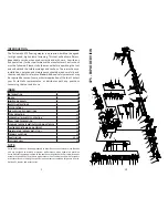
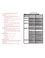
• Air pressure too low.
• Staple crown above tongue.
• Increase air pressure.
• Air pressure too high.
• Staple buried.
• Lower air pressure.
• Correct air pressure.
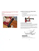
• Staple just below surface.
FLOOR
STAPLE
7
prior to making any modi
fi
ca
ti
ons to the tool.
Other Detailed Informa
ti
on
Refer to the tool maintenance instruc
ti
ons for detailed informa
ti
on
on the proper maintenance of the tool.
Actua
ti
on System
This tool u
ti
lizes a dual trigger single sequen
ti
al actua
ti
on system.
The contact safety located in the nose of the tool must be held
depressed and either of the two triggers pulled to actuate the tool.
The trigger must be pulled for each subsequent actua
ti
on provided
that the contact safety remains depressed against the work piece
for subsequent actua
ti
ons. The contact safety is included to prevent
accidental actua
ti
on of the tool.
D
o not defeat or disable the contact
safety.
Power Source
The compressed air power source shall be pressure-regulated. The
regulated pressure must not exceed the maximum air pressure
marked on the tool. If a regulator fails, the pressure delivered to the
tool must not exceed 1.5
ti
mes the maximum air pressure, or 200
PSI
G
, whichever is greater. The tool normally is not operated at the
maximum air pressure but at a lower pressure determined by the
type of fastener used, the work piece, and other condi
ti
ons. of use.
Hazardous Power Source
Hazardous power sources shall not be used. Hazardous power
sources include, but are not limited to the following:
Reac
ti
ve gases including, but not limited to oxygen and
•
combus
ti
ble gases.
Pressure sources that can deliver in excess of 1.5
ti
mes the
•
maximum air pressure of the tool or 200 PSI
G
, whichever is
greater, if a regulator fails.
Regulator
Pressure regulators shall be used to limit the air pressure supplied
to the tool. Regulators shall be set at an opera
ti
ng pressure which is
lower than or equal to the tool manufacturer’s speci
fi
ed maximum
air pressure.
Hose


