


Operation
Atlas
®
Digital Amplifier Complete Technical Reference
47
4
To read the instantaneous actual state of the operating mode, the command
GetActiveOperatingMode
is used.
4.5.2
Individual Phase Control
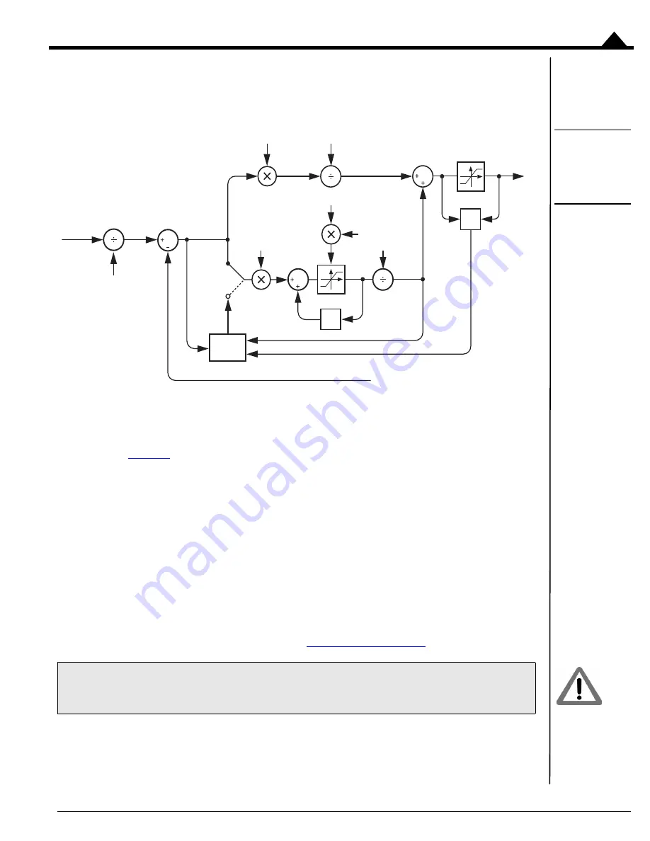
Figure 4-6:
Individual
Phase Control
Calculation
Flow
When individual phase control mode is selected Atlas utilizes the commanded current for each motor winding
provided by the commutation module, along with the actual measured current provided by circuitry within the power
stage, to perform current loop calculations.
As can be seen in
, the desired current and measured current are subtracted to develop a current error, which
is passed through a PI (proportional, integral) filter to generate an output voltage command for each motor coil. The
output command for each coil is then passed to the power stage module to generate precise PWM (pulse width
modulation) output signals, representing the applied voltage, that control the power stage’s switching bridge.
To enable individual phase control the command
SetCurrentControlMode
is used. The value set using this
command can be read back using
GetCurrentControlMode
.
Three parameters are set by the user to control the current loop;
Kp
,
Ki
, and
Ilimit
. Two of these are gain factors for
the PI controller, and the other is a limit for the integral contribution.
To set any of these three parameters the command
SetCurrentLoop
is used. To read back these parameters, the
command
GetCurrentLoop
is used. For multi-phase motors, the values for the phase A and B loops can be set
independently while for single-phase DC brush motors, only the phase A loop parameters are used. The values set
using this command are buffered, meaning they are held by Atlas in a buffer but do not instantaneously become active.
Buffered commands are activated using the SPI Header. See
It is the responsibility of the user to determine control parameters that are suitable for use in a given application.
256
256
Output
< >
Ki
Kp
ILimit
PWM
Limit
64
Command
Anti
Windup
Actual
Current
Reference
Error
Integrator
Sum
2
Z
-1


