

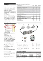

BLUEPORT® FRONT INTERFACE
Connection to the controller front via a
PC adapter (see ‘Additional Accesso-
ries’). The BlueControl
®
software en-
ables the KS 45 to be configured,
parameters set, and operated.
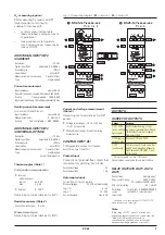
BUS INTERFACE (OPTIONAL)
RS 485
Connection via bus connector fitted in
the top-hat rail. Screened cables
should be used.
Galvanically isolated
Type:
RS 485
Transmission speed:
2,400, 4,800, 9,600, 19,200,
38,400 bits/sec
Parity:
even, odd, none
Address range:
1...247
Number of controllers per bus segment:
32
Protocol:
•
MODBUS RTU
SYSTEM INTERFACE
For connection to fieldbus couplers
(see system components)
Connection via bus connector fitted in
the top-hat rail.
Technical data see data sheet
9498-737-50911.
ENVIRONMENTAL CONDITIONS
Protection mode
Front panel:
IP 20
Housing:
IP 20
Terminals:
IP 20
Permissible temperatures
For specified accuracy:
-10...55°C
Warm-up time:
< 20 minutes
Temperature effect:
ß
0.05 % / 10 K
add. influence to cold
junction compensation:
ß
0.05% / 10 K
Operating limits:
-20...60°C
Storage:
-30...70°C
Humidity
Max. 95%, 75% yearly average, no
condensation
Shock and vibration
Vibration test Fc (DIN EN 60 068-2-6)
Frequency:
10...150 Hz
Unit in operation:
1g or 0.075 mm
Unit not in operation:
2g or 0.15 mm
Shock test Ea (DIN EN 60 068-2-27)
Shock:
15 g
Duration:
11 ms
Electromagnetic compatibility
Complies with EN 61 326-1 for conti-
nuous, unattended operation.
Interference radiation:
•
Within the limits for Class B devices.
Immunity to interference:
Meets the test requirements for devi-
ces in industrial areas.
Evaluation criteria:
•
Surge interference partly has marked effects,
which decay after the interference stops.
•
With high levels of surge interference on 24 V
AC mains leads, it is possible that the device
is reset.
•
With HF interference, effects up to 50 µV can
occur.
GENERAL
Housing front
Material:
Polyamide PA 6.6
Flammability class:
VO (UL 94)
Connecting terminals
Material:
Polyamide PA
Flammability class: V2 (UL 94) for screw terminals
V0 (UL 94) for spring-clamp
terminals and bus connector
Electrical safety
Complies with EN 61 010-1
Over-voltage category II
Contamination degree 2
Protection class II
Electrical connections
Plug-in connector strips with choice of
terminal type:
•
Screw terminals or spring-clamp
terminals, both for lead
cross-sections from 0.2 to 2.5 mm
2
.
(AWG24-12)
Mounting method
Clip-on rail mounting (35 mm top-hat
rail to EN 50 022).
Locked by means of metal catch in
housing base.
Close-packed mounting possible.
Mounting position:
vertical
Weight:
0.18 kg
Standard accessories
•
Operating instructions
•
With ‘Interface’ option: bus
connector for fitting into top-hat rail
CERTIFICATION
•
CE certified
•
DIN 3440 / EN 14597
•
UL/cUL certified
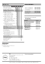
6
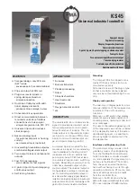
KS 45
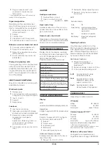
117.5 (4,63”)
99
(3,90”)
2.3
22.5
111 (4,37”)
5.5
(0,87”)
(0,08”)
(0,20”)
Klemme
/
terminal
15
16
17
18
5
6
7
8
1
2
3
4
11
12
13
14
Klemme
/
terminal
Fig. 4: Overall dimensions (in mm)


