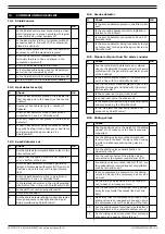
0507347110/160114/B SHIELD fire safety solutions (5k1)
| INSTALLATION | EN - 7
5.4
Electrical connection
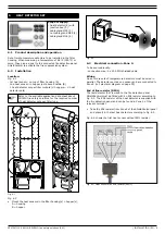
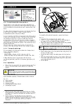
Fig. 5.3
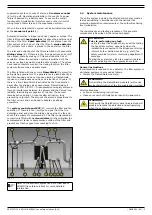
ShieldControl (D) must be wired to:
- heat detector set(s) (J)
- spark detector set (H)
- smoke detector (I)
- fire alarm sounder (included in ShieldControl package) (C)
- manual call point (included in ShieldControl package) (B)
- system control panel SCP (E)
ShieldControl activates:
- FlameShield fire extinguishing generator(s) (A)
- fire alarm sounder (C)
- system control panel SCP (E)
System control panel SCP (E) activates:
- sliding valves (G)
- solenoid valve (F)
Fig. 5.3
All connections for field wiring are to the terminal strips along
the top and bottom of the PC board.
Cables to be used:
- 5 x 20 AWG shielded cable for detectors and manual call point
- 5 x 20 AWG normal cable for other wiring
The resistance of any core of any cable should not exceed 25
ohm(>1640 ft for 20 AWG).
To connect the cables to the ShieldControl panel, use suitable
metal cable glands fitted to the knock-outs provided.
•
Connect all cables to the ShieldControl panel in accordance
with the electrical diagram on page 29.
The wiring of the detectors, manual call point, FlameShield and
fire alarm sounder is monitored for open circuit fault conditions.
5.4.1
Battery packs
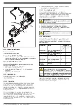
The ShieldControl panel is fitted with battery leads wired to the
PC board to connect the two battery packs.
•
Place both battery packs inside the ShieldControl panel.
•
Connect them to the battery leads.
5.4.2
Mains supply
The mains supply of 115V/230V AC must be connected to a
clean group or to a group that is not connected to equipment
likely to cause frequent power failures.
•
Connect the ShieldControl panel to the mains in accordance
with the electrical diagram on page 29.
5.5
Maintenance
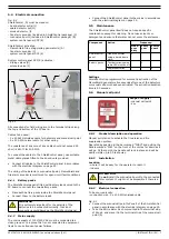
The ShieldControl panel itself does not require specific
maintenance except for cleaning. Do not use solvents or
detergents and ensure that water cannot enter the enclosure.
Settings
ShieldControl is programmed for automatic activation of the
FlameShield generators five seconds after one of the detectors
or manual call point has been activated. The activation duration
time is 60 seconds.
5.6
Manual call point
5.6.1
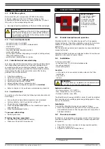
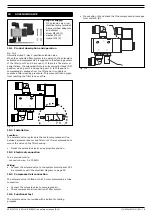
Product description and operation
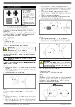
Manual pull station to activate the fire alarm and fire
suppression system.
Operated by pushing in the bar marked “PUSH” and pulling the
handle marked “PULL” on the front of the unit as far down as it
will go. At that point, the handle will lock in place and will be
easily visible up to 50 feet away.
5.6.2
Installation
Location
- where it will be easy for the operator to reach it
- indoors
5.6.3
Electrical connection
To be sourced locally:
- connection wire: 5 x 20 AWG shielded cable
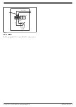
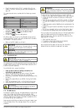
Connect the manual call point to Zone 4 of the ShieldControl
panel in accordance with the electrical diagram on page 29.
•
Take the EOL resistor 5k ohm mounted in the terminal strip
of Zone 4 and place it in the terminal strip of the manual call
point (A).
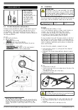
WARNING
It is extremely important for the polarity of the
batteries to be connected correctly. Incorrect
connections could damage the ShieldControl panel.
E
F
A
B
C
D
F
J
I
H
Component
Action
Frequency:
when-
ever
dirty
every
year
every 4
years
ShieldControl
panel
Clean the outside
using a barely damp
cloth.
X
Battery packs
Test batteries;
POWER
FAULT
LED must be off.
X
Replace batteries.
X
Scope of supply:
- manual call point
- key
ATTENTION
Do
not
install the manual call point to the connected
filter system. It might not be accessible if there is a
fire.


