background image

User Interface (GUI) - Operator Menu

Plockmatic PowerSquare™ 160 - Service Training Workbook 

25

4.9

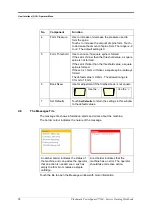
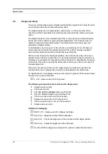
The Message Window


The message window shows

1. an error code
2. the area of the machine
3. the message text

See ‘Message List’ in the Operator Manual for more details.
If you need to request technical support, make sure you know the error code(s).

4.10

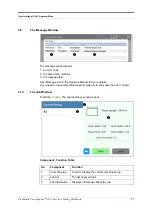
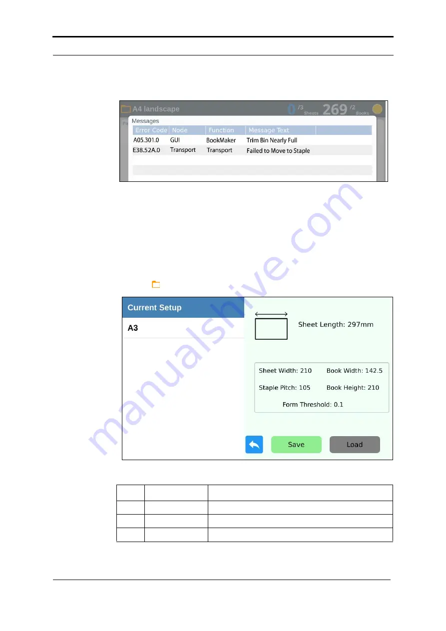
The Job Window

Touch the 

 icon. The Job load/save window opens.


Component - Function Table

No.

Component

Function

1

Current Setup

Touch to display the current machine setup.

2

Job List

The list of saved jobs.

3

Job Information

Displays information about the job.

Summary of Contents for Morgana PowerSquare 160

Page 1: ...Plockmatic PowerSquare 160 Right to Left Service Training Workbook for Konica Minolta Issue 1 Published October 2018 Amended 27 02 2019 Name Doc No x05081...

Page 2: ...s document is subject to change without notice Watkiss Automation Limited makes no warranty of any kind with regard to this material including but not limited to the implied warranties of merchantabil...

Page 3: ...16 3 8 Outfeed and Stacker 17 4 User Interface GUI Operator Menu 18 4 1 Introduction 18 4 2 Illustration Online 18 4 3 Illustration Hand Feed 19 4 4 Window Controls 20 4 5 The Paper Size Window 21 4...

Page 4: ...ansport Book Gathering 36 8 5 Paper Transport Book Transport 37 8 6 Staple and Clinch 38 8 7 Fold and Form 39 8 8 Trim 41 8 9 Outfeed and Stacker 42 9 Preventative Maintenance 43 9 1 Operator Maintena...

Page 5: ...oduction Plockmatic PowerSquare 160 Service Training Workbook 1 1 Introduction Figure 1 Plockmatic PowerSquare 160 Right to left with connecting bridge Figure 2 Plockmatic PowerSquare 160 Hand feed mo...

Page 6: ...ombines the four processes of stapling folding spine forming and trimming to produce SquareBack books up to 160 pages With a maximum book thickness of 8 mm 40 sheets 80gsm the PSQ160 is a fast and cos...

Page 7: ...Conventions in this workbook The Plockmatic PowerSquare 160 is referred to by its code of PSQ160 this is an instruction or task that the trainer will do this is a task that the student will do This wo...

Page 8: ...Base Machine PWAS Waste Bin Assembly PDEC Deck assembly PSK Stacker PGUI GUI and Hinge Assembly PFOL Folder Assembly PFRL Fold Rollers Assembly PFOR Spine Former PSTO Trim Stop PTRI Trimmer POUT Outf...

Page 9: ...02 WASHER M2 5 FORM A STAIN LESS 1 1c 258 223 ST STEEL PDEC PIVOT LOCATION PLATE 1 1d 266 088 SHAFT PSQ ACTIVE GATE PIVOT PIN 1 2 100 406 SCREW SKT HD CAP M3x8 HT ZP 4 3 160 002 WASHER M3 FORM A BZP 1...

Page 10: ...cting bridge See Section 3 1 The paper is rotated in the connecting bridge if necessary See Section 3 1 The sheets of paper are flipped upside down and gathered into a set in the gathering area See Se...

Page 11: ...fold blade lifts and the form clamp closes The form roller creates the SquareBack spine on the book See Section 3 6 The fold rollers drive the book down to the trim infeed where the book is driven ont...

Page 12: ...matic PowerSquare 160 Service Training Workbook The book is released and conveyed by the outfeed mechanism to the stacker See Section 3 8 The finished books are stacked neatly ready for the operator t...

Page 13: ...connecting bridge by belts into the gathering area Paper can be accepted from either side referenced or centre referenced printers The connecting bridge translates the paper to centre referenced for t...

Page 14: ...60 sends an error message to the printer The print job and the PSQ160 stop An optical sensor in the uplift infeed sees that a piece of paper has entered the uplift module Another optical sensor at the...

Page 15: ...Square 160 Service Training Workbook 11 3 2 The Gathering Area Online Figure 7 Paper enters the infeed face up Figure 8 Paper is gripped and rotated by the infeed drum A Infeed B Paper face up C Clamp...

Page 16: ...s and sidelays The endlays and sidelays are adjusted by the PSQ160 to the measured paper size entered into the touch screen Adjustments to the sidelays and endlays are made with stepper motors See Fig...

Page 17: ...ove to the correct position Paper is placed into the gathering area between the endlays and sidelays See Figure 10 If the machine is configured for Auto Sensor then after a preset delay the set will b...

Page 18: ...he machine knows the position of the flights and can then adjust the position as needed for different sizes of paper Additionally one flight per side has a magnetic index pin that is seen by a sensor...

Page 19: ...the staples and folds the book in half The folder blade pushes the book to a calculated depth between a pair of fold rollers and into the form clamp Each face of the form clamp has a horizontal polyu...

Page 20: ...ide and the spine form clamp is released The fold rollers rotate to drive the book through to the trimmer infeed conveyors An optical sensor in the fold area sees when paper is present If the sensor s...

Page 21: ...sferred from the main electric motor by a chain and clutch system Rotary movement is changed to linear movement with a crank mechanism 3 8 Outfeed and Stacker When the trim clamp is released a stepper...

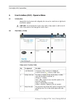
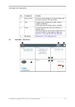
Page 22: ...h screen 4 2 Illustration Online Component Function Table No Component Function 1 Job Information The name of the current job is displayed Touch the job icon to save or load a job 2 Status Indicator T...

Page 23: ...mber 5 Tiles The tiles display information about the machine condition and setting Touch a tile to open a window with more details 6 Clock The clock is shown when the user interface is in Operator mod...

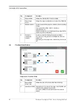
Page 24: ...e machine is running Amber attention Operator action is needed 3 Book Counter The book counter shows the number of books made To reset the counter touch the number 4 Tiles The tiles display informatio...

Page 25: ...ange of values is shown at the top Touch to confirm the setting and close the keypad If an illegal value is entered the top panel will turn from blue to red Icon Function No Component Function 1 Stand...

Page 26: ...is automatically on Rotation allows to you to feed paper long edge first for optimum printer productivity 8 Portrait or Landscape selector Touch to select the finished booklet orientation The red line...

Page 27: ...sted and Auto and ON OFF options are available 6 Side Trim ON OFF 7 Height Offset If the optional P2T Side Trimmer is installed an offset of up to 40mm can be applied up or down depending on the amoun...

Page 28: ...e spine is formed If the set is thinner than the threshold value a square spine is not formed If the set is thicker than the threshold value a square spine is formed If the set is 1 5mm or thicker a s...

Page 29: ...xt See Message List in the Operator Manual for more details If you need to request technical support make sure you know the error code s 4 10 The Job Window Touch the icon The Job load save window ope...

Page 30: ...sk for technical support If you touch this tile the System Status window opens with additional information See Section 4 12 System Status Window Configuration tile Shows how the machine is configured...

Page 31: ...s A3 Test A Status column One column for each node B 2 colour indicator for motor with sensor C Red indicator D Green indicator E Grey indicator Offline or not available Indicator Description Sensor n...

Page 32: ...made Perform the following tasks Load the saved A3 Test job Use 40 sheets A3 paper 80gsm Make the book Delete the saved job Load the saved A4 Test job Use 20 sheets A4 paper 80gsm Make the book Delet...

Page 33: ...A dirty sensor or a sensor covered by paper trimmings will give a jam error 5 4 Book Quality and Machine Specifications Quality tolerance specification is included in this training workbook see Sectio...

Page 34: ...he service functions on the User Interface provide counters for sheets books staples form and trim cycles calibration configuration settings and machine options machine status information including er...

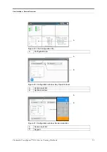
Page 35: ...Service Training Workbook 31 Figure 19 The Configuration tile Figure 20 Configuration window Key Operator level Figure 21 Configuration window Service selection A Configuration tile A Access level li...

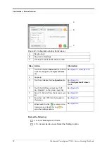
Page 36: ...and hold the Advanced tile until the clock tile changes to the System Status tile See Figure 17 and Figure 18 2 Swipe up 3 Touch and release the Configuration tile See Figure 19 The Configuration Win...

Page 37: ...y installed With the training instructor review the following ADJ 4 11 6 Check and Adjust the Bridge for Level ADJ 4 11 10 PSQ160 to Bridge Alignment Vertical ADJ 4 11 5 Check and Adjust the PSQ160 fo...

Page 38: ...ne for the Rotate axis and one for the Centre axis The rotator and uplift conveyor motors run when the PSQ160 starts The sheets are transported past 2 optical sensors in the rotator and 2 optical sens...

Page 39: ...g area module accepts the paper from the connecting bridge When the correct number of sheets has arrived the paper transport moves the set to the staple area see Section 8 4 The following components a...

Page 40: ...mper gate in the front sidelay jogs the incoming sheets into a tidy set When the set is complete the active tamper gate lifts to let the set move to the staple position Optical sensors in the infeed t...

Page 41: ...Each flight has a metal reference pin that interrupts optical sensors as the belts move From this the machine knows the position of the flights and can then adjust the position as needed for differen...

Page 42: ...contact the set The steps needed to bring the clinchers to the paper are counted and compared with the zero point to calculate the thickness of the book This data is used by the folder and former to...

Page 43: ...ansported on a carriage that runs along the carriage guide The carriage drive is from a stepper motor When the carriage reaches the end of the carriage guide either the Form roller end A or Form rolle...

Page 44: ...Workbook Perform the following ADJ 4 7 1 Check the Fold Blade to Staple Alignment ADJ 4 7 2 Adjust the Fold Blade to Staple Alignment ADJ 4 9 3 Check the Alignment of the Form Clamp to the Staple Posi...

Page 45: ...e trim bin by flexible fingers on one of the trimmer infeed conveyor shafts The drive for the trimmer blade and the trim clamp is transferred from the main electric motor by a chain and clutch system...

Page 46: ...elt A conveyor moves the books from the PSQ160 and drops them on the catch tray An adjustable collection table makes sure the finished books stack correctly There is an optical sensorin the outfeed to...

Page 47: ...ed Conveyors and Trimmings Removal Fingers 4 23 8 Clean the Polyurethane Strips in the Form Clamp 9 2 Technical Maintenance The recommended service interval is every 12 months In addition after 1 mill...

Page 48: ...rter The reactor has 3 independent inductive coils it s a 3 phase device of which 2 are used through which the supply voltage is passed to the motor drive i e the inverter and motor The reactor can fi...

Page 49: ...es Each node has a unique number See Table 1 and Figure 24 The GUI provides overall control and user input The other nodes control local functions but are instructed from the GUI and sensor input Tabl...

Page 50: ...3 Transport Module Electrical Layout Diagram 7 2 5 Bridge Electrical Layout Diagram Inverter GUI Rotate 900 308 PCB M Stepper Motor Sensors CAN Bus M Stepper Motors Sensors Uplift 900 310 PCB Staple...

Page 51: ...C filter Terminal Block Reactor Lenze i510 inverter Interlock relay 3 way IEC socket 26V DC power supply 46V DC power supply 15V DC power supply 900 316 Power Communications Distribution PCB Fuse hold...

Page 52: ...Power and Control 48 Plockmatic PowerSquare 160 Service Training Workbook Figure 25 Electrical box Overview Item Description A B C D E F G H J K D E F G H C B A J K...

Page 53: ...Power and Control Plockmatic PowerSquare 160 Service Training Workbook 49 Figure 26 Electrical box Behind the mains inlet Item Description A B C D E A B C D E...

Page 54: ...Power and Control 50 Plockmatic PowerSquare 160 Service Training Workbook Figure 27 Electrical box Rear view Item Description A B C D A B C D...

Page 55: ...must be ON to let the PSQ160 run online LEDs are GREEN LED1 ST0 S0 LED off Offline LED9 CMD0 C0 Sheet exit LED2 ST1 S1 LED off Fault LED10 CMD1 C1 End of set LED3 ST2 S2 LED off Full LED11 CMD2 C2 Cyc...

Page 56: ...an application which allows the download of updates 11 2 Software Update Software can be downloaded via an internet connection or a media device An Upgrade Net or Upgrade USB command checks current ma...

Page 57: ...ically or saved locally This can be requested as part of a service call escalation The support file contains all the event data generated by the PSQ160 6 12 Send a Support File 6 12 1 Procedure the ma...

Page 58: ...eplace the Trimmer Blade and Anvil 13 PSQ160 Accessories The following optional accessories for the PowerSquare are documented in separate Computer Based Training courses CBTs If time permits a short...

Page 59: ...x 252mm Minimum rotation sheet size 215 x 200mm The cross track dimension of the sheet before rotation must be at least 7mm greater than the in track dimension Sheet Feed Orientation Cover first face...

Page 60: ...or right hand input module Input height to match the printer Input speed adjustable Optional pass through module to support in line operations with an added DFA device Comms Interface DFA compliant En...

Page 61: ...ration 700VA 500W Noise Emission standby ambient in operation 69 dB A peak 75 dB A Approvals Complies with CE and T V UL Conforms to FCC rules Part 15 Class A and VCCI Class A Patents GB 2360013 EP 11...

Page 62: ...flat so they cannot cause injury Legs should not re penetrate the spine Spine forming The quality of the SquareBack spine is subjective and is operator adjustable Its purpose is to produce a book wit...

Page 63: ...s 830 mm wide The PBS Book Stacker is L shaped Dependent on access it may fit through a standard size doorway The P2T 2 Knife Trimmer is 565mm wide without the outfeed table If the equipment is instal...

Page 64: ...imensions Length Width Height Weight PSQ160 online 2090 mm 83 940 mm 37 1560 mm 62 525 kg 1155 lb PBR 7xR connecting bridge right to left 1180 mm 47 900 mm 36 1350 mm 54 139 kg 307 lb PBS Book Stacker...

Page 65: ...Power Supply 220 240V 50 60 Hz single phase Protection Fuse 2 X F3 0A HRC Connection Power input from PowerSquare 160 Consumption standby 35VA 16W in operation 75VA 53W Item Specification Supply A sin...

Page 66: ...ockmatic PowerSquare 160 Service Training Workbook 16 11 Online PSQ160 R2L PSQ160 Connecting Bridge Input for Mains Power Supply Maintenance area 2995 mm 2495 mm 1760 mm Maintenance area 2750 mm NOT T...

Page 67: ...PowerSquare 160 Service Training Workbook 63 16 12 Online PSQ160 R2L with PBS Bookstacker PSQ160 Connecting Bridge Book Stacker Input for Mains Power Supply Maintenance area 2775 mm 2275 mm 2300 mm Ma...

Page 68: ...60 Service Training Workbook 16 13 Online PSQ160 R2L with P2T 2 Knife Trimmer PSQ160 Connecting Bridge P2T Trimmer Input for Mains Power Supply Input for Mains Power Supply Maintenance area 3540 mm 30...

Page 69: ...rvice Training Workbook 65 16 14 Online PSQ160 R2L with P2T and PBS PSQ160 Connecting Bridge P2T Trimmer Input for Mains Power Supply Book Stacker Input for Mains Power Supply Maintenance area 3315 mm...

Page 70: ...han height The opposite of portrait loop omega A type of staple that is shaped like the Greek letter omega Used when book lets are to be placed in a ring binder moving clinch The clinch bends the legs...

Page 71: ...ding side of a book let SquareBack Name of a book which has a stapled square spine Technology developed and patented by Watkiss Related terms Square fold term used to describe the Plockmatic product w...

Page 72: ...Glossary of booklet making terms 68 Plockmatic PowerSquare 160 Service Training Workbook...

Page 73: ......

Page 74: ......

Page 75: ......

Page 76: ...Watkiss Automation Limited 1 Blaydon Road Middlefield Industrial Estate Sandy Bedfordshire SG19 1RZ United Kingdom Tel 44 0 1767 685700 Fax 44 0 1767 689900 Email info watkiss com Web www watkiss com...

Reviews:

Related manuals for Morgana PowerSquare 160