background image

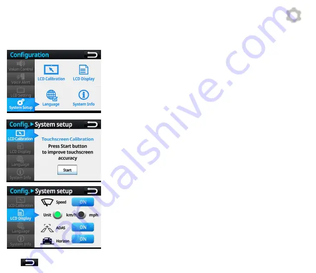
4) System Setup


LCD Calibration : Calibrate touchscreen for its accuracy 

LCD Indication : Speed UI , smart UI and horizon guide line can be 
turned ON/OFF. 

Language Setting : The UI language can be selected.  

System Info : Check system info or reset system 

4-2) LCD Indication  


Speed : If ON, it shows speed value on LCD  

Unit : Select the type of speed unit 

Smart Function : If ON , ADAS UI appears on LCD.  

Horizontal Line : If ON , a horizontal guide line appears in live-view mode. 

*             : Return to the previous menu 

[Configuration] 

4-1) LCD Calibration  


Start : press to calibrate touchscreen 

Press (+) in sequence to complete LCD calibration process 

32 

Summary of Contents for Optian

Page 1: ...1...

Page 2: ...opy modify or translate this manual without any prior consent ADAS or Advanced Driver Assistance System is an advanced safety assist system that can help a driver to avoid or mitigate accidental colli...

Page 3: ...ppendix Certificate Specification Warranty Contents 1 Safety Caution Warning Caution 2 Accessories Functions 3 Product Installation 4 Main Functions Basic Option Main Body HUB and Pin map Secondary ex...

Page 4: ...arge or fire User is responsible for the damage in this case Do not install the product in a location where it interferes with driver s vision Do not change settings while driving as it may cause traf...

Page 5: ...cro SD Card from the manufacturer to avoid product damages Do not remove SD card when the product is operating as it may cause product damage Only remove the Micro SD card when the product is powered...

Page 6: ...ged improperly When the calibration is incorrect ADAS functions only work when the speed rate received from GPS is over the set operating speed threshold If the speed data cannot be received properly...

Page 7: ...hange without a prior notice The above images are for user s understanding actual accessories may look a little different OLED Display Optional Vibrator Basic and Optional Accessories HUB Secondary Ca...

Page 8: ...Body Touch LCD Bracket Power Port Mini USB type Micro SD Front Camera FHD Secondary Camera 2 5 External GPS 3 5 USB Port External WiFi Connection Micro SD Card socket Volume Adjustment Recording Butt...

Page 9: ...tivate parking mode CCTV it is necessary to connect wires to ACC and B If there is no need for parking mode CCTV connect twisted ACC and B wires to ACC only B WIPER Speed are optional connections No S...

Page 10: ...Secondary Camera The specific installation location of Secondary Camera can be set by the user A 5m power cable is provided Integral Bracket DC Power Port DC Power Cable 10...

Page 11: ...loser to the bottom area of windscreen in heavy vehicles Sedan RV Bus Truck Reflections of objects may affect the video quality and ADAS performance Avoid placing or installing reflective objects on t...

Page 12: ...ongly adjusted Guide line is below the horizon Bad If the calibration is not done on flat ground ADAS functions may not perform properly Ensure to calibrate camera when parked on flat ground After the...

Page 13: ...around 1 min on the road with clear lane markings in order to automatically calibrate the camera ADAS functions may not work ideally if the automatic calibration is not completed 2 Remove tape off br...

Page 14: ...and B After installation drive 60km h for around 1 min on the road with clear lane markings in order to automatically calibrate the camera ADAS functions may not work ideally if the automatic calibrat...

Page 15: ...If camera is reset in shaky conditions ADAS may not work properly After installation drive 60km h for around 1 min on the road with clear lane markings in order to automatically calibrate the camera A...

Page 16: ...de Avoid installing directly over heat wires Caution Ensure to connect the secondary camera after turning off the power of the main body The secondary camera may not be sensed if it is connected when...

Page 17: ...en changing lanes without turning indicator light ON Continuous lane changing within 2 seconds will not activate the alarm Accompanied by a Strong LDW Alarm the violated direction of icon appears in R...

Page 18: ...signal if a risk of impending crash is detected The collisional risk is estimated by calculating the relative speed and the distance to a preceding vehicle Accompanied by a series of Strong FCW Alarm...

Page 19: ...ming is estimated by calculating driving speed and the distance to a preceding vehicle Accompanied by a notifying sound timing indication ex 0 7sec 0 9sec In Monitoring Display Mode 2 The SDA function...

Page 20: ...If the distance to the vehicle in front is less than 3 meters it gives a VB warning The collisional risk is estimated by calculating the distance to the vehicle in front Accompanied by a VB alarm A ve...

Page 21: ...fies the driver The change of distance to a front vehicle is monitored when the host vehicle is stationary Accompanied by a notifying sound A vehicle icon appears in GREEN in Monitoring Display Mode 2...

Page 22: ...e detected The full body shape of an adult pedestrian should be visible The maximum detection range is up to 20 meters which may vary by installation positions Accompanied by a PCW alarm A pedestrian...

Page 23: ...es 3 parking mode CCTV The parking mode CCTV can be activated when ACC IG and B are connected If the vehicle engine is turned off it will enter into the parking mode CCTV If the vehicle engine is turn...

Page 24: ...ing up When power is applied the intro loading screen will appear Loading Screen Even the system is connected to B of vehicle the system will restart when turning on vehicle IG System Start Logo Scree...

Page 25: ...e A Red vehicle icon will appear when generating a FCW signal A Red pedestrian icon will appear when generating a PD warning Number on Left Shows the vehicle speed 80 as shown in the image The horizon...

Page 26: ...ed SDA Timing it indicates timing value at the center of image FCW A vehicle icon appears in Red FCDA A vehicle icon appears in Green Pedestrian Detection A pedestrian icon appears in Green PCW A pede...

Page 27: ...operations 2 DVR Change settings of recording mode and format SD card 3 Play Video Check and play recorded files 4 Configurations Configure system volume voice alarm and other system settings 5 Vehic...

Page 28: ...row to change adjustable from 20 to 80 km h Sensitivity the default setting is 0 7 sec adjustable from 0 4 sec to 1 0 sec A higher value can enable a more responsive warning 3 LDW Operating Start Spee...

Page 29: ...pacity of Micro SD card The number of stored files may vary by remaining capacity Resolution Continuous Event Parking Remark Full HD 100min 30min 120min 1CH 16GB Full HD 200min 60min 120min 1CH 32GB F...

Page 30: ...n When pressing stop button it will return to the file selection page scroll upward downward to change play the selected video file User can check recorded video files with ease via PC Data Manager pr...

Page 31: ...alarm can triggered when an event occurs Voice Alarm Only voice message can be triggered when an event occurs FCW and VB only generate sound alarms without voice messages 3 Display Setting View Mode S...

Page 32: ...nfo Check system info or reset system 4 2 LCD Indication Speed If ON it shows speed value on LCD Unit Select the type of speed unit Smart Function If ON ADAS UI appears on LCD Horizontal Line If ON a...

Page 33: ...efault language is in Korean user can select English or Japanese in the menu 4 4 System Info Check version info of FW HW and MCU Press Reset button to remove all saved system parameters The Installati...

Page 34: ...Height will be automatically set as follows in Dimensions menu For more accurate warnings it is recommended to input actual values of Width or Height in Dimensions menu Vehicle Type Setup Installation...

Page 35: ...the arrow which is opposite to the applied direction of turn signal blinks continuously please change High Low settings of Blinker Active in the Dimensions menu Measure the height from the ground to...

Page 36: ...e Libraries x86 guide 3 Install PC viewer by following install guide 4 A desktop icon will be created after installation If Google Map is not supported by your internet explorer the map will not appea...

Page 37: ...ar 6 Video Play Menu Bar 7 Video Play Time 8 Video Volume 9 Speed Indication 10 Compass 11 Recorded Date GPS co ordinates 12 Acceleration sensor data impact level speed graph 13 Play DIT Mode Change 1...

Page 38: ...cation tracking window 4 ADAS display screen 5 Manager Menu bar 6 Video Play Bar 7 Video Play Time 8 Video Volume 9 Speed Indication 10 Compass 11 Recorded Date GPS co ordinates 12 Acceleration sensor...

Page 39: ...DIT mode Acceleration Impact Speed graph in detail Change to Player mode Acceleration value press to switch to G sensor button Indicate vehicle tracking mark G sensor impact level press to change to...

Page 40: ...normal video recording process a blinking REC appears on the LCD display If REC does not appear the SD card may have an error Please format or replace the SD card Overwrite and Data Backup SD card ha...

Page 41: ...FF automatically at high temperature in parking mode CCTV to ensure stable recording Q No ADAS warnings Check if ADAS functions are turned OFF Check if the volume level is set at 0 Check GPS status an...

Page 42: ...icles traffic signs and pedestrians Optional Devices UI Meaning Number SDA timing Orange REC Recording Activated Green Vehicle Vehicle Detection Warning Lane Icon Lane Detection Warning PD Icon Pedest...

Page 43: ...hrough the instant vibratory warning method The vibration strength can be adjusted from level 1 to level 3 or can be turned off Strength Adjustment Lever How to use vibratory device Place the vibrator...

Page 44: ...Certification Appendix...

Page 45: ...y 25 fps 6 Video H 264 Extension AVI 7 Voice Recording condenser MIC 8 Display 3 5 TFT Touch LCD 9 External GPS GPS GLONASS receiver 10 Memory Micro SD 16GB Minimum 4 GB Maximum 128 GB 11 External Con...

Page 46: ......

Reviews: