background image

13

To achieve a sound performance that is correctly aligned to your room, make sure all of the leads carrying
signals for the RIGHT channel loudspeaker are connected to the RIGHT input to the amplifier from your
preamplifier or CD player etc.  Signals for the LEFT channel should be wired in a similar fashion.

CONNECTING THE MAINS SUPPLY

Now that your Plinius 8200 Integrated Amplifier is configured to your system correctly, the mains cable
can be plugged into the IEC socket on the back of the amplifier.  Ensure that the processor switch on the
back panel is correct for your intended usage (normally ‘bypass’), and check the speaker cables are
connected correctly.  Flick the power switch on the front panel to the right.  The power LED will pulse for
five seconds as the internal microprocessor allows the internal circuitry to stabilise before opening the
mute circuit.  You can now enjoy your new Plinius 8200 Integrated Amplifier.

WARM-UP PERIOD

You will find that the Plinius 8200 will become noticeably ‘warmer’ in sound after being on for a period of
time.  We usually recommend waiting at least 24 hours before expecting the best quality of sound
reproduction from your amplifier.  Also, as the Plinius 8200 uses very little power while on, we suggest
leaving the unit turned on so that it will always be at it’s sonic best.

Summary of Contents for 8200 MkII

Page 1: ...C l a s s A B I n t e g r a t e d A m p l i f i e r...

Page 2: ...2...

Page 3: ...the variety of ways it may be used We have designed and manufactured this amplifier to reproduce faithfully and accurately your favourite music With a little care and a full understanding of the oper...

Page 4: ...er Features Front Panel Page 6 Amplifier Features Rear Panel Page 8 Installation and Operation Page 10 Input Output Connection Page 11 8200 Features Page 14 Loudspeaker Selection Page 16 Specification...

Page 5: ...ier operates at hazardous voltage levels There are some alterations that may be made by you the owner However we recommend that any work requiring removal of the lid be referred to a suitably qualifie...

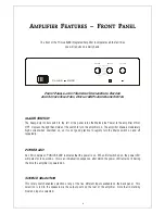
Page 6: ...he amplifier on The amplifier draws a moderately high current when switched on so it is not good practice to rapidly turn the Mains switch on and off repeatedly POWER LED An LED in between PLINIUS 820...

Page 7: ...TROL KNOB The volume control is an ALPS motorised unit that will accurately convey the source signals to the power amplification stage of the Plinius 8200 The knob can be adjusted manually or with the...

Page 8: ...IN OUT PHONO CD TUNER TAPE 1 PRE OUT PROCESSOR TAPE 2 MUTE RIGHT CHANNEL LEFT CHANNEL PROCESSOR BYPASS ONLY IN RIGHT CHANNEL FUSES LEFT CHANNEL FUSES REAR PANEL SHOWING INPUT AND OUTPUT TERMINALS MUT...

Page 9: ...sor PROCESSOR SWITCH This switch is used in conjunction with the processor source and return terminals and controls whether the amplifier is used via the normal inputs or the processor return input PR...

Page 10: ...for further advice if required MAINS VOLTAGE CONNECTION Firstly check that the mains supply voltage printed on the rear of this amplifier is similar to the mains supply voltage in your area If in doub...

Page 11: ...he external processor s input to processor source on the back of the Plinius 8200 Next connect the external processor s output channel that the Plinius 8200 will power i e front rear centre or sub to...

Page 12: ...ignal from whatever the source selector knob is currently set to TERMINATION QUALITY Quality of the connections must be examined to ensure that high performance trouble free operation is enjoyed Check...

Page 13: ...correct for your intended usage normally bypass and check the speaker cables are connected correctly Flick the power switch on the front panel to the right The power LED will pulse for five seconds a...

Page 14: ...board The gain can now be adjusted noting that high gain factory setting is set with jumpers to the left and low gain is set with jumpers to the right Now re assemble your Plinius 8200 TAPE LOCKOUT PR...

Page 15: ...NIUS PLINIUS PLINIUS PLINIUS dealer MAINS LINE FUSE A Mains Line fuse is fitted within the IEC socket on the rear of the amplifier A small drawer at the bottom of this socket may be removed after the...

Page 16: ...hase As a general rule the use of high power 200 Watt RMS or greater loudspeakers is recommended and desirable However our experience indicates that medium to low power loudspeakers 100 to 200 Watt RM...

Page 17: ...w gain setting 0 75mV on Phono high gain setting S I II INPUT NPUT NPUT NPUT I II IMPEDANCE MPEDANCE MPEDANCE MPEDANCE 47k S I II INPUT NPUT NPUT NPUT O O O OVERLOAD VERLOAD VERLOAD VERLOAD 5V RMS S P...

Page 18: ...Pages 5 10 Output Terminals Pages 8 11 Phasing Page 12 Phono Earth Post Page 9 Phono Gain Adjustment Page 14 Phono Inputs Page 8 Placement Pages 5 10 Pre Out Output Pages 9 12 Processor Connections Pa...

Page 19: ...hnologies Ltd Audible Technologies Ltd Audible Technologies Ltd Audible Technologies Ltd P O Box 18 P O Box 18 P O Box 18 P O Box 1836 36 36 36 Palmerston N Palmerston N Palmerston N Palmerston North...

Reviews: