background image


Accessory Kit Contents 

One (1) power cable 
One (1) Ethernet cable 
Four (4) SATA II data cables 
One (1) external audio extension cable 


One (1) remote control 
One (1) USB mouse 
One (1) CD containing the DVR manual, client software and software tools 
One (1) package of HDD installation screws, rack mounting brackets, etc 
 
Note:  The contents of the accessory kit are subject to change without notice 

HDD Installation 

If your DVR was ordered with a hard disk drive (HDD) preinstalled, you may skip this step.  This 
procedure may also be used at a future date to add additional storage capacity to your DVR.  Please 
refer to the User’s Manual for recommended HDD brands and models. 
 
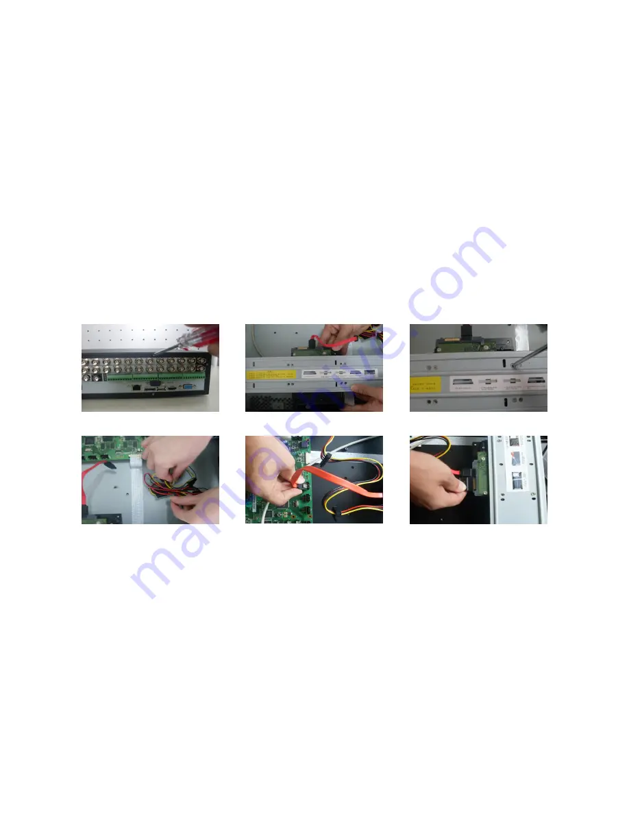
Please follow the instructions below to install/add a HDD. 


Remove the top cover from the 
DVR. 

Align the HDD with the holes 
provided on the HDD bracket. 

Using four screws, attach the 
HDD to the bracket. 


Unfasten the HDD power cable.  Attach the SATA cable to the 

HDD and to the system board. 

Attach the power cable to the 
HDD. 

Rack Installation 

The DVR will occupy two units of vertical rack space (2U). 


Attach the rack mount brackets to the DVR using 3 screws each provided in the accessory 
kit. 


Mount the DVR within the rack using 4 screws (not provided). 


Always mount equipment within a rack from the bottom up. 


If possible, it is advised to leave one rack unit of space between devices for ventilation. 


Ensure that the temperature is below 95° Fahrenheit (35° Celsius). 


Always ensure that sufficient power is provided for electronic components and that the power 
is conditioned using a surge protector or uninterruptable power supply (UPS). 


Summary of Contents for IntelliPix

Page 1: ...Platinum Class IntelliPix User Manual ...

Page 2: ...anel 5 Connection Sample 6 Alarm RS 485 Connection Block 6 Overview of Navigation and Controls 7 Login Logout Main Menu 7 Login 7 Main Menu 8 Logout 8 Auto Resume after Power Failure 8 Recording Operation 9 Live Viewing 9 Status Icons 9 Recording Setup Schedule 9 Schedule Menu 9 Manual Record Menu 10 Encode 10 Snapshot 11 Snapshot Image Storage 12 Search and Playback 12 Basic Operation 13 Network ...

Page 3: ...surge suppressor or power conditioning device DVR Repairs Examination and repair work on the DVR should be done by qualified service engineers Unauthorized repair work or modifications may void any warranty agreements We are not liable for any problems caused by unauthorized modifications or repairs Environment The DVR should be installed in a cool dry area away from direct sunlight The DVR should...

Page 4: ...low to install add a HDD Remove the top cover from the DVR Align the HDD with the holes provided on the HDD bracket Using four screws attach the HDD to the bracket Unfasten the HDD power cable Attach the SATA cable to the HDD and to the system board Attach the power cable to the HDD Rack Installation The DVR will occupy two units of vertical rack space 2U Attach the rack mount brackets to the DVR ...

Page 5: ...Receives input from the remote control Shuttle Outer ring In monitor mode clockwise will move forward one channel or set of channels and counter clockwise will move backward one channel or set of channels In menu mode clockwise will move to the next menu option and counter clockwise will move to the previous menu option In playback mode clockwise will cycle fast forward speed and counter clockwise...

Page 6: ...hange the current playback window to the next channel Window view selector Mult Cycles the monitor view to the next window view mode Alarm output control Alarm Brings up the Alarm menu Manual record control Rec Brings up the Manual Record menu Function assistant Fn In full screen monitor mode brings up the Assist Function menu When entering text used as a backspace key When used to configure motio...

Page 7: ...nel 13 into single full screen view In playback mode used as a toggle to add 10 to the channel to be viewed for the time period matching the search result Back Panel The rear panel of the DVR is displayed below Please refer to the following table for rear panel details Item Number Description 1 Power switch 2 Power cord input 3 Power supply fan 4 Individual channel loop outputs 5 Audio input for c...

Page 8: ...VGA video output port 17 Alarm RS 485 connection block 18 Composite video output port 19 Composite video matrix output port Connection Sample The following is a sample of devices that may be connected to your DVR Alarm RS 485 Connection Block The Alarm RS 485 Connection Block is displayed below ...

Page 9: ...up the default video display is in multiple window live display mode Press Enter or left click the mouse to bring up the login interface By default the DVR has four accounts Username admin Password admin administrator local and network Username 888888 Password 888888 administrator local only Username 666666 Passwords 666666 Unprivileged user who can only monitor playback backup and etc Username de...

Page 10: ...information or detail which is stored per unit of time of a recording A higher bit rate will allow a better image to be produced but will use more resources such as HDD storage and network bandwidth Audio Video You can enable audio for the main stream or video audio for the extra sub stream Video for the main stream is always enabled by default and is not configurable For extra stream enable the v...

Page 11: ...o configure or select ALL if you want to configure all channels identically This field will display channel 1 by default Week day Each day of the week may be configured individually There are eight options Sunday through Saturday and ALL This field will display the current day of the week by default Pre record This value sets the amount of time to pre record before a motion detection or alarm even...

Page 12: ...ecord or select Advanced Manual Record to go to the Manual Record menu The selections from this menu are the highest priority for recording There are three status options Schedule Manual and Stop Highlight the icon to select the option for the corresponding channel The following is a description of the configurable options Manual The selected channels will begin regular continuous recording after ...

Page 13: ...information or detail which is stored per unit of time of a recording A higher bit rate will allow a better image to be produced but will use more resources such as HDD storage and network bandwidth Audio Video You can enable audio for the main stream or video audio for the extra sub stream Video for the main stream is always enabled by default and is not configurable For extra stream enable the v...

Page 14: ...information or detail which is stored per unit of time of a recording A higher bit rate will allow a better image to be produced but will use more resources such as HDD storage and network bandwidth Audio Video You can enable audio for the main stream or video audio for the extra sub stream Video for the main stream is always enabled by default and is not configurable For extra stream enable the v...

Page 15: ...lowing table for control reference Basic Operation There are multiple search parameters video type channel number and time The DVR can display a maximum of 128 results for one search Use the page up down button if there is more than one page Normal Playback Number Function 1 Play 2 Reverse 3 Stop 4 Slow play 5 Fast play 6 Previous frame 7 Next frame 8 Volume 9 Previous file 10 Next channel 11 Next...

Page 16: ... s in the search results list Next click backup button to proceed to the backup menu Slow playback and fast playback Refer to the following table for slow and fast playback functions Button Illustration Remarks Fast play button In playback mode click this button to switch between the 4 available fast playback speeds such and normal playback mode Slow play button In playback mode click this button ...

Page 17: ... information automatically Use of DHCP to acquire a dynamic IP address is not recommended TCP port Default TCP communications port value is 37777 UDP port Default UDP communications port value is 37778 HTTP port Default HTTP TCP communications port value is 80 Max connection The DVR can support a maximum of 10 concurrent user connections 0 means there is no connection limit Transfer mode Select th...

Page 18: ...s the following items Please select channel first Protocol Select corresponding PTZ protocol such as PELCOD Address Input corresponding PTZ address Baud rate Select the baud rate Data bit Select the number of data bits Default value is 8 Stop bit Select the number of stop bits Default value is 1 Parity Select the parity There are three choices none odd even Default value is none After configuring ...

Page 19: ...tion There are a total of 8 directional arrows If you use remote control you can only use four directions up down left and right You can click the Set button or click REC button in the front panel to set preset tour and pattern for the PTZ You can click the Page Switch button or click Fn button in the front panel to change PTZ function interfaces ...

Page 20: ...mple if your DVR IP address is 10 10 3 16 enter http 10 10 3 16 in the address column The system will display warning information to confirm that you wish to install the webrec cab control Please click yes button If you can t install the ActiveX file please modify your IE security setup see User s Manual for more information on this After installation the interface is shown as below Input your use...

Page 21: ......

Reviews: