background image

5

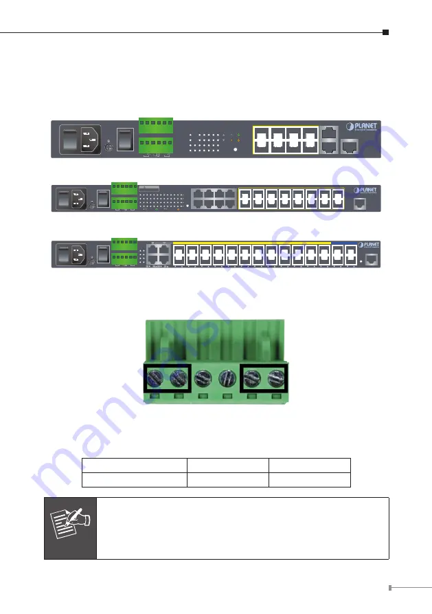
3. Wiring DC Power Inputs

The  Front  Panel  of  the  Managed  Metro  Switch  indicates  a  DC  inlet  power  socket 
and  consists  of  one  terminal  block  connector  within  6  contacts.  Please  follow  the 

steps below to insert the power wire.

1

3

5

7

2

4

6

8

Ring

PWR

DC 1 Owner

DC 2

Fault

ACT

LNK

ACT

LNK

1000

100

RESET

10

9

MGSD-10080F

2

1

4

3

6

5

8

7

10

Console

115200,N,8,1

9

100~240V AC

50/60 Hz

ON

AC POWER

OFF

DC POWER

ON

DC Input Range 36V~60V

OFF

Fault

GND

GND

DO 1

DO 0

DI 1

DI 0

DC 2

DC 1

V1+

V2+

Figure 3-1:

  MGSD-10080F Switch Front Panel

100~240V AC

50/60 Hz

ON

OFF

DC POWER

ON

OFF

Reset

10

12

14

16

9

11

13

15

18

20

22

24

17

19

21

23

2

4

6

8

1

3

5

7

ACT

1000 LNK

ACT

10/100 LNK

Console

115200, N, 8, 1

18 20 22 24

2

Fault

DC1

DC2

PWR

4

6

8 10 12 14 16

17 19 21 23

1

3

5

7

9 11 13 15

MGSW-24160F

Fault

GND

GND

DO 1

DO 0

DI 1

DI 0

DC 2

DC 1

DC Input Range: 36V~60V DC

Please refer to user’s manual before

connect the DC wire.

CAUTION

Figure 3-2:

  MGSW-24160F Switch Front Panel

100~240V AC

50/60 Hz

ON

AC POWER

OFF

DC POWER

ON

OFF

Ring R.O.

Fault

FAN2

FAN1

PWR

DC 2

DC 1

DC Input Range:

36V~60V

2

4

6

8

10

12

14

16

18

20

22

24

26

28

27

26

25

24

23

22

21

20

19

18

17

16

15

14

13

12

11

10

9

8

7

6

5

4

3

2

1

28

Console

Reset

115200, N, 8, 1

Fault

GND

GND

DO 1

DO 0

DI 1

DI 0

DC 2

DC 1

1

2

3

4

2

4

MGSW-28240F

Figure 3-3: 

 MGSW-28240F Switch Front Pan

el

Tighten the wire-clamp screws for preventing the wires from loosening.

1

2

3

4

5

6

V1+ V1-

V2+ V2-

Power 1

Power 2

Positive (+) Pin

Negative (-) Pin

Managed Metro Switch

Pin 1 / 5

Pin 2 / 6

Note

The wire gauge for the terminal block should be in the range from 

12

 to 

24

 AWG.

Summary of Contents for MGSD SERIES

Page 1: ...Managed Metro Ethernet Switch MGSW MGSD Series Quick Installation Guide...

Page 2: ...erminal Setup 6 4 1 Logging on to Console 7 4 2 Configuring IP Address 8 4 3 Storing Current Switch Configuration 9 5 Starting Web Management 10 5 1 Logging in to the Managed Metro Switch 10 5 2 Savin...

Page 3: ...00 1000T Managed Metro Ethernet Switch Managed Metro Switch is used as an alternative name in this Quick Installation Guide Open the box of the Managed Metro Switch and carefully unpack it The box sho...

Page 4: ...ch as Tera Term PuTTY or Hyper Terminal included in Windows XP 2003 Serial cable one end is attached to the RS232 serial port while the other end to the console port of the Managed Metro Switch z z Et...

Page 5: ...8 20 22 24 2 Fault DC1 DC2 PWR 4 6 8 10 12 14 16 17 19 21 23 1 3 5 7 9 11 13 15 MGSW 24160F Fault GND GND DO 1 DO 0 DI 1 DI 0 DC 2 DC 1 DC Input Range 36V 60V DC Please refer to user s manual before c...

Page 6: ...ial Port RS232 to RJ45 Cable Console Port RJ45 Figure 4 1 Managed Metro Switch Console Connectivity A terminal program such as Tera Term or PuTTY is required to make the software connection to the Man...

Page 7: ...assword are shown as follows and the login screen in Figure 4 3 appears Username admin Password admin Figure 4 3 Managed Metro Switch Console Login Screen The user can now enter commands to manage the...

Page 8: ...ws Showing the Current IP Address 1 At the prompt enter show ip interface brief 2 The screen displays the current IP address as shown in Figure 4 4 Figure 4 4 IP Information Screen Configuring IP Addr...

Page 9: ...P address 4 3 Storing Current Switch Configuration In the Managed Metro Switch the running configuration sequence running config can be saved from the RAM to FLASH by copy command so that the running...

Page 10: ...1 and 254 except 100 and the default subnet mask is 255 255 255 0 PC Workstation with Web Browser 192 168 0 x Managed Switch RJ45 UTP Cable IP Address 192 168 0 100 Figure 5 1 IP Management Diagram 5...

Page 11: ...ddress 192 168 0 100 Default Username admin Default Password admin Figure 5 2 Login Screen 3 After entering the password the main screen appears as Figure 5 3 shows Figure 5 3 Web Main Screen of Manag...

Page 12: ...efresh Save Help and Logout Figure 5 4 Switch Menu Figure 5 5 Switch Menu System Note If you are not familiar with Switch functions or the related param eter press Help icon anytime on the Web page to...

Page 13: ...rtup configuration on the Web user interface the startup configuration file will be loaded automatically across a system reboot 1 Click the Save icon on the top Switch Menu bar 2 Press the Save Config...

Page 14: ...the management Web interface within the same subnet of 192 168 0 xxx Reset 115200 N 8 1 MGSW 28240F 100 240V AC 50 60 Hz ON AC POWER OFF DC POWER ON OFF DC Input Range 36V 60V Reset Button Figure 6 1...

Page 15: ...ww planet com tw en support faq Switch support team mail address support planet com tw MGSW MGSD series User s Manual https www planet com tw en support downloads method keyword keyword M GS view 3 li...

Page 16: ......

Reviews: