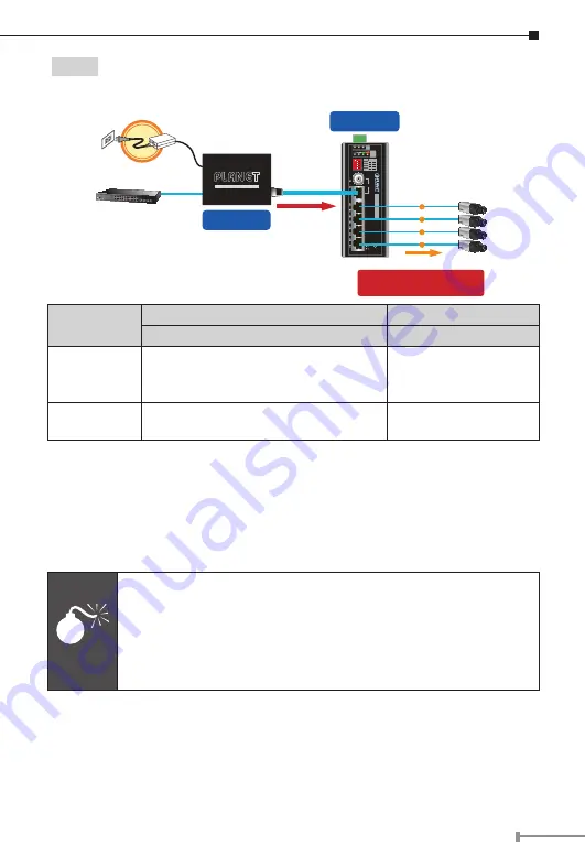
Planet LRP-104CET User Manual Download Page 23

23

 Type 2

  LRP-101UH with 48~56V power adapter and LRP-104CET with PoE 

power output

802.3af/802.3at PoE

PoE IP Camera

LRP-104CET

Long Reach PoE Extender

P1

P2 Fault

PWR

LNK

LRP IN

4

3

2

1

LRP-104CET

Ext.

PWR

10W 20W 30W 40W

PoE

Power

Usage

ACT

LNK
PoE In-use

ON
ON
ON
ON

OFF
OFF
OFF
OFF

1

Port

PoE

2
3
4

Long Reach PoE


Extender

1

2

3

4

OFF

PoE

PoE

PoE

PoE

Remote LRP Power over UTP

PoE Power Budget

60 watts~120 watts (max.)

Ethernet Switch

110-240V AC

AC-to-DC Adapter

60W~120W/48~56V DC IN

Cat5e/6

Power over UTP

LRP-101UH

Long Reach PoE Injector

Long Reach Power over Ethernet

Functions

LRP Injector

LRP Extender

LRP-101UH

LRP-104CET

Power Input

Power adapter

 with 

48~56V DC

 in

The LRP-101UH accepts up to 120W 
external power input

UTP

 with DC power 

over UTP input

Power Output

UTP

 with DC power over UTP output

RJ45

 with 802.3at/af 

PoE output

Installation Instructions

Step 1.

  Remove the “Danger – No Ethernet” label stuck on the RJ45 LRP 

ports of LRP-101UH.

Step 2.

 Connect the LRP Injector (LRP-101UH) and LRP Extender 

(LRP-104CET) to ends of RJ45 terminated long UTP/twisted-pair 
cable.

Warning

1. Please do not connect any Ethernet equipment to LRP 

OUT Port of the LRP-101UH; otherwise, it will damage the 
Ethernet equipment.

2. Please do not connect any Ethernet equipment to LRP IN Port 

of the LRP-104CET; otherwise, it will damage the Ethernet 
equipment.

Step 3.

  Connect Cat5/6 UTP cable to LRP-101UH and non-PoE switch or 

workstation.

Step 4.

  Connect 48~56V DC power adapter to LRP-101UH power socket, and 

then the PWR LED of LRP-101UH and LRP-104CET should be lit up 
immediately.

Step 5.

 Connect Cat5/6 UTP cable to LRP-104CET and IEEE 802.3at/af 

complied PoE IP camera or PoE Wireless AP.

Summary of Contents for LRP-104CET

Page 1: ...Industrial 1 Port Coax UTP Long Reach PoE 4 Port 10 100TX PoE Extender LRP 104CET User s Manual...

Page 2: ...ications 11 5 Installation Precautions 15 5 1 Installation Precautions of Remote Power by Coaxial Cable 15 5 2 Installation Precautions of Remote Power by UTP Cable 15 5 3 Installation Precautions of...

Page 3: ...ox of the LRP Extender and carefully unpack it The box should contain the following items LRP Extender x 1 User s Manual x 1 DIN Rail Kit x 1 Wall mount Kit x 1 If any of these are missing or damaged...

Page 4: ...the following application topologies users can find the suitable way to extend the distance and power on the remote PDs 2 1 Point to Multi point Remote LRP Power through BNC RJ45 with DC 56V input or...

Page 5: ...30W 40W PoE Power Usage ACT LNK PoE In use ON ON ON ON OFF OFF OFF OFF 1 Port PoE 2 3 4 Long Reach PoE Extender 1 2 3 4 OFF PoE PoE PoE PoE Remote LRP Power over UTP PoE Power Budget 60 watts 120 wat...

Page 6: ...ts max 110 240V AC PoE IP Camera LRP 822CS Power over Coaxial 802 3at PoE Up to 400m Up to 400m UTP PoE PoE PoE PoE UTP PoE PoE PoE PoE 120W 24 48V DC Power Supply 120W 24 48V DC Power Supply DC DC P1...

Page 7: ...Mounting Kit Mounting Kit DIN Rail Kit Side View Rear View Input DC 24 48V DC1 DC2 Fault P1 P2 Fault PWR LNK LRP IN 4 3 2 1 LRP 104CET Ext PWR 10W 20W 30W 40W PoE Power Usage ACT LNK PoE In use ON ON...

Page 8: ...LNK LRP IN 4 3 2 1 LRP 104CET Ext PWR 10W 20W 30W 40W PoE Power Usage ACT LNK PoE In use ON ON ON ON OFF OFF OFF OFF 1 Port PoE 2 3 4 Long Reach PoE Extender 1 2 3 4 OFF Figure 3 2 LRP 104CET Front P...

Page 9: ...is 30W 40W Green Lights to indicate the power usage is 40W LRP Interface LED Color Function PWR Green Lights to indicate the power is on LNK Green Lights to indicate that the Coaxial UTP link is estab...

Page 10: ...Port 1 PoE Disable Port 2 ON default Port 2 PoE Enable OFF Port 2 PoE Disable Port 3 ON default Port 3 PoE Enable OFF Port 3 PoE Disable Port 4 ON default Port 4 PoE Enable OFF Port 4 PoE Disable Not...

Page 11: ...et Plus PSE PoE Type End span PoE Power output 52V DC PoE output depends on LRP Injector or LRP Switch 52V DC 25 watt per port External DC input Cabling Ethernet 10BASE T 2 pair UTP Cat 3 4 and 5 Ethe...

Page 12: ...put 1 312ft Max 1000m without PoE output 3 280ft Max 100m with PoE output 328ft Max 400m with PoE output 1 312ft Long Reach Ethernet Standard IEEE 1901 Modulation Type Wavelet OFDM Security 128 bit AE...

Page 13: ...C power over coaxial input DC 24 48V redundant power with polarity reverses protection function Power Consumption Dissipation 130watts 446BTU Ethernet with PoE Full Loading Alarm One relay output for...

Page 14: ...20W 14W 16W 120W 600m 66 67 Mbps 19W 10W 12W 120W 800m 48 57 Mbps 11W 7W 8W 120W 1000m 44 57 Mbps 5W 120W UTP Performance Distance Data rate Upload Download 802 3af at PoEtotal Output Capability Remo...

Page 15: ...tion After the power over coaxial injector is enabled the center pin of the coaxial cable is with electricity Please do not touch the center pin W a r n in g T h is s id e o f c o n n e c to r c o n t...

Page 16: ...cted with an external power supply the LRP 104CET will give priority to external power supply LRP Injector or LRP Switch where data is transmitted to the LRP 104CET Caution When performing any of the...

Page 17: ...r will detect the fault status of the power failure and then forms an open circuit The following illustration shows an application example for wiring the fault alarm contacts 1 2 3 4 5 6 Fault Alarm C...

Page 18: ...ch with coaxial cable Type 1 One LRP 101CH with PoE power input and one LRP 104CET with PoE power output The LRP Injector is powered via IEEE 802 3at af PoE An IEEE 802 3at af compliant PoE PD will au...

Page 19: ...with PoE power output The LRP Injector is powered via the external power adapter The IEEE 802 3at af compliant PoE PD will automatically be powered by the LRP Extender via UTP 802 3af 802 3at PoE PoE...

Page 20: ...input cannot be used if power input of DC 52V or 56V is selected Type 3 One LRP 822CS LRP 1622CS with AC power input and one LRP 104CET with PoE power output The LRP Switch is powered via the AC power...

Page 21: ...ion of LRP Switch LRP 822CS LRP 1622CS from WebUI the PWR LED of LRP 104CET should be lit up immediately Step 4 Connect Cat5 6 UTP cable to LRP 104CET and IEEE 802 3at af complied PoE IP camera or PoE...

Page 22: ...Please do not connect any Ethernet equipment to LRP IN Port of the LRP 104CET otherwise it will damage the Ethernet equipment Step 3 Connect Cat5 6 UTP cable to LRP 101UH and IEEE 802 3at compliant P...

Page 23: ...ith DC power over UTP input Power Output UTP with DC power over UTP output RJ45 with 802 3at af PoE output Installation Instructions Step 1 Remove the Danger No Ethernet label stuck on the RJ45 LRP po...

Page 24: ...2 3af 802 3at PoE PoE IP Camera 120W 24 48V DC Power Supply LRP 104CET Long Reach PoE Extender P1 P2 Fault PWR LNK LRP IN 4 3 2 1 LRP 104CET Ext PWR 10W 20W 30W 40W PoE Power Usage ACT LNK PoE In use...

Page 25: ...PoE Power Usage ACT LNK PoE In use ON ON ON ON OFF OFF OFF OFF 1 Port PoE 2 3 4 Long Reach PoE Extender 1 2 3 4 OFF P1 P2 Fault PWR LNK LRP IN 4 3 2 1 LRP 104CET Ext PWR 10W 20W 30W 40W PoE Power Usa...

Page 26: ...er P1 P2 Fault PWR LNK LRP IN 4 3 2 1 LRP 104CET Ext PWR 10W 20W 30W 40W PoE Power Usage ACT LNK PoE In use ON ON ON ON OFF OFF OFF OFF 1 Port PoE 2 3 4 Long Reach PoE Extender 1 2 3 4 OFF 120W 24 48V...

Page 27: ...I Media Dependent Interface MDI X Media Dependent Interface Cross PoE 1 Tx transmit Rx receive Positive VCC 2 Tx transmit Rx receive Positive VCC 3 Rx receive Tx transmit Negative VCC 4 5 Not used Not...

Page 28: ...3 White Green 4 Blue 5 White Blue 6 Green 7 White Brown 8 Brown 1 White Orange 2 Orange 3 White Green 4 Blue 5 White Blue 6 Green 7 White Brown 8 Brown SIDE 1 SIDE 2 1 White Orange 2 Orange 3 White Gr...

Reviews: