Planet LRE-101 User Manual Download Page 15

15

5. Applications

The  Ethernet  Extender  does  not  require  any  software  configuration.  Users  can 

immediately use any feature of this product simply by attaching the cables 
and turning the power on. There are some key limitations on the Ethernet 
Extender. Please check the following items.

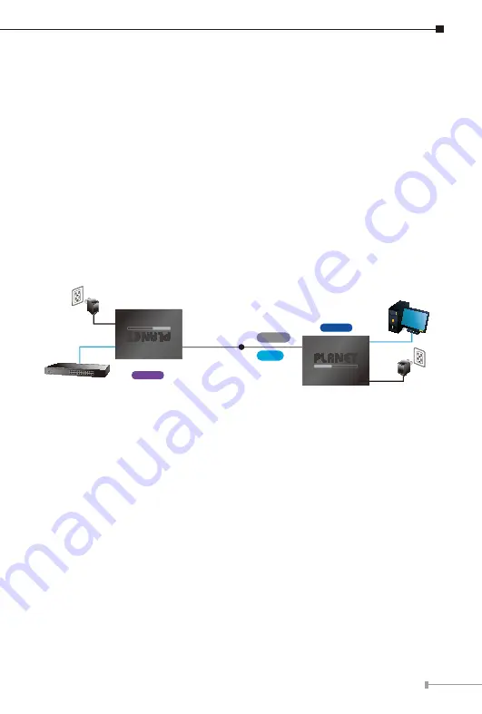
5.1  Point-to-Point Application -- LAN to LAN Connection

One set of the Ethernet Extender could be used to link two local area networks 

that  are  located  in  different  places.  Through  the  UTP  cable  or  Phone  wire,  it 
could set up a 100Mbps backbone, but one Ethernet Extender must be Master 

(CO mode) and the other one is Slave (CPE mode).

Point to Point Application 

5V DC adapter

Switch

PC

LRE-101

Master

LRE-101

Slave

5V DC adapter

or

Phone wire Up to 

12000m

Cat5E UTP Up to 

700m

Connecting Standalone PC

Refer to the following procedures to set up the LRE-101 LAN to LAN 
connection.

1. [LAN1] Set the LRE-101 in LAN 1 to be in the 

Master

 mode from the DIP 

switch

2. [LAN2] Set the LRE-101 in LAN 2 to be in the 

Slave

 mode from the DIP 

switch

3. Power  on  the  LRE-101  Master  and  Slave  at  both  sides  by  connecting  its 

power source.

4. Master or Slave LED will illuminate correspondingly.
5. Connect  UTP  cable  or  Phone  wire  from  LAN1  LRE-101  to  UTP  port  of  the 

LAN2 LRE-101.

6. LNK LED will blink to illuminate at both LRE-101 units.
7. Connect the LRE-101 Ethernet LAN port to other network device via regular 

Cat5 UTP cable or Phone wire.

Summary of Contents for LRE-101

Page 1: ...1 Port 10 100TX over UTP Long Reach Ethernet Extender LRE 101 User s Manual...

Page 2: ...this User s Manual PLANET makes no commitment to update or keep current the information in this User s Manual and reserves the right to make improvements to this User s Manual and or to the products...

Page 3: ...e radio interference Energy Saving Note of the Device This power required device does not support Standby mode operation For energy saving please remove the power cable to disconnect the device from t...

Page 4: ...cations 10 4 Installations 12 4 1 Wall mount Installation 12 4 2 Chassis Installation and Rack Mounting 13 4 3 Optional DIN rail Installation 14 5 Applications 15 5 1 Point to Point Application LAN to...

Page 5: ...101 Open the box of the Ethernet Extender and carefully unpack it The box should contain the following items LRE 101 DC 5V 2A Power Adapter If any of these are missing or damaged please contact your d...

Page 6: ...nsions Dimensions W x D x H 94 x 70 3 x 26 2mm 26 20 94 00 70 30 46 70 7 00 Unit mm 5V DC Master Slave Long Reach Ethernet 10 100TX over UTP Extender Long Reach Ethernet over UTP Extender LRE 101 LNK...

Page 7: ...d whole system System LED Color Function PWR Green Lit Indicates that the Ethernet Extender has power Off Indicates that the Ethernet Extender has no power Long Reach Ethernet interface LED Color Func...

Page 8: ...DC input for power adapter DIP Switch The Ethernet Extender provides a selectable 2 position DIP switch When switching to Master it supports PtP meaning it can be one master and one slave DIP Function...

Page 9: ...resentative 2 5mm DC Receptacle 2 5mm 5V for each slot DC receptacle is 2 5mm wide that conforms to the Ethernet Extender 2 5mm DC jack s central post Do not install any improper unit In some areas in...

Page 10: ...45 copper port Cabling Cat5 UTP cable Phone wire Maximum Distance Max 800m with data transmission Cat5 UTP 1200m with data transmission Phone wire Long Reach Ethernet Standard IEEE 1901 Modulation Typ...

Page 11: ...Compliance IEEE 802 3 802 3u Ethernet standard compliant IEEE 802 3x Full duplex flow control IEEE 802 1q Tag VLAN Transparent Multicast pass through Regulatory Compliance FCC Part 15 Class A CE Envir...

Page 12: ...two screws on the wall Step 3 Hang the LRE 101 on the screws from the wall Step 4 Repeat Step 5 of Desktop Installation for power supply to the LRE 101 10GBASE T to 10GBASE X 5V DC Before mounting the...

Page 13: ...e slot of the converter chassis Step 3 Attach a rack mount bracket to each side of the Converter Chassis with supplied screws attached to the package Step 4 After the brackets are attached to the Conv...

Page 14: ...RKE DIN can be ordered separately Refer to the following steps for the DIN rail mounting of the LRE 101 Step 1 Screw the DIN rail on the LRE 101 Step 2 Now slide the DIN rail into the track Step 3 Ch...

Page 15: ...ave CPE mode Point to Point Application 5V DC adapter Switch PC LRE 101 Master LRE 101 Slave 5V DC adapter or Phone wire Up to 12000m Cat5E UTP Up to 700m Connecting Standalone PC Refer to the followi...

Page 16: ...set up an IP surveillance system with many pairs of the LRE 101 1 Set the LRE 101 to be in the Master or Slave mode from the DIP switch on the rear panel 2 Power on the LRE 101 by connecting its powe...

Page 17: ...r Upstream Downstream Unit Mbps 200 81 80 400 59 52 600 52 44 800 28 22 1000 48 36 1200 11 6 Cat5 Distance meter Upstream Downstream Unit Mbps 200 89 88 400 60 58 600 29 29 800 14 33 The actual data r...

Page 18: ...NT 1 Verify you are using the Cat5e or better cable with RJ45 connector to connect to the port 2 If your device like LAN card supports auto negotiation please try to manu ally set at a fixed speed of...

Page 19: ...19 8 FAQs Q1 What is the best distance for LRE 101 A1 In order to guarantee the stability and better quality of network we suggest the distance should not exceed 700m Cat 5 UTP and 1200m Phone wire...

Page 20: ...need more support information please contact PLANET switch support team PLANET online FAQs https www planet com tw en support faq Switch support team mail address support planet com tw Copyright PLANE...

Reviews: