background image

19

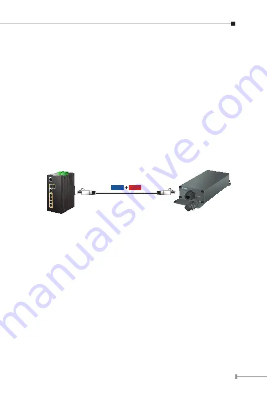
2.5 Connecting IPOE-E172 to Power Source Equipment 

(PSE)

This section describes how to install Industrial Ultra PoE Extender and 
make connection to it. Please read the following topics and perform the 
procedure in the order being presented.

There are 3 RJ45 ports in the Industrial Ultra PoE Extender of which 
the 

“PoE IN”

 port functions as 

“PoE (Data and Power) input”

 and 

the 

“PoE-in-Use”

 port on the other side functions as 

“PoE (Data and 

Power) output”

.

Step 1:

  Connect a standard Cat5e/6 UTP cable from 

power source 

equipment (PSE)

, such as PoE switch, PoE injector hub and 

single port PoE injector, to the 

“PoE IN”

 port of the IPOE-

E172.

802.3bt PSE/PoE Switch

IPOE-E172

Power

Data

100m

Step 2:

  The PSE delivers both Ethernet Data and PoE power over 

UTP cable to the IPOE-E172 and the 

“PoE IN”

 LED will be lit 

steadily.

Summary of Contents for IPOE-E172

Page 1: ...Industrial 1 port Ultra PoE to 2 port 802 3bt at Gigabit PoE Extender IPOE E172 User s Manual...

Page 2: ...mes no responsibility for any inaccuracies that may be contained in this User s Manual PLANET makes no commitment to update or keep current the information in this User s Manual and reserves the right...

Page 3: ...l effects on the environment and human health as a result of the presence of hazardous substances in electrical and electronic equipment end users of electrical and electronic equipment should underst...

Page 4: ...2 Installation 12 2 1 Physical Dimensions 12 2 2 Front Panel 13 2 3 Rear Panel 14 2 4 Mounting Installation 14 2 4 1 Making Waterproof RJ45 Cable 15 2 4 2 Wall Mounting 16 2 4 3 Connecting Waterproof...

Page 5: ...retain the carton including the original packing material and use them again to repack the product in case there is a need to return it to us for repair 1 2 Product Features Physical Port 3 10 100 100...

Page 6: ...uplex and 1000Mbps full duplex mode flow control auto negotiation and auto MDI MDI X Features Store and Forward mode with wire speed filtering and forwarding rates IEEE 802 3x flow control for full du...

Page 7: ...1 3 Product Specifications Model IPOE E172 Hardware Specifications Network Connector PoE In Port 1 x 10 100 1000BASE T Ethernet with 802 3bt at PoE Data Power in auto MDI MDI X auto negotiation RJ45 c...

Page 8: ...W x D x H 199 6 x 81 x 40 mm Weight 373g Power Consumption 60 watts 204BTU Full loading with PoE function Power over Ethernet PoE Standard PoE In Port IEEE 802 3bt at Power over Ethernet end span mid...

Page 9: ...ture 40 75 degrees C Relative Humidity 5 95 non condensing Storage Temperature 40 85 degrees C Relative Humidity 5 95 non condensing Accessory Standard Accessories User s Manual x 1 Waterproof RJ45 Co...

Page 10: ...tion will be below 60 watts if with PoE PSE 1 5 Power over Ethernet Capability With different distance and different PoE input source it will inflect the PoE output capability Please refer to the tabl...

Page 11: ...V A Distance B Distance C Watts 60M 2M 50 60M 20M 48 60M 60M 39 60M 100M 34 100M 2M 44 100M 20M 39 100M 60M 33 100M 100M 28 Note The table list shown here is for your reference only The actual perform...

Page 12: ...l it Basic knowledge of networking is assumed Please read this chapter completely before continuing 2 1 Physical Dimensions IPOE E172 industrial 1 port Ultra PoE to 2 port 802 3bt at Gigabit PoE Exten...

Page 13: ...r receiving data over that port 1000 Green Lights to indicate the IPOE E172 is successfully connecting to the network at 1000Mbps Off to indicate the IPOE E172 is successfully connecting to the networ...

Page 14: ...up at 10 100 1000Mbps Blinks to indicate that the IPOE E172 is actively sending or receiving data over that port PoE in Use Orange Lights to indicate the port is providing PoE power Off to indicate t...

Page 15: ...ep 1 Take a waterproof RJ45 jack out from the IPOE E172 box and prepare one RJ45 cable Step 2 Insert the RJ45 cable through the waterproof RJ45 jack Step 3 Prepare an RJ45 connector Step 4 Put the RJ4...

Page 16: ...g or damage please contact your local reseller where you purchased from If the new waterproof RJ45 connector is obtained from PLANET make sure its dimensions are the same 3 Never use any waterproof RJ...

Page 17: ...the box Step 2 Place the IPOE E172 on the wall Step 3 Use a screwdriver to screw them into the wall 2 4 3 Connecting Waterproof RJ45 Connector to the IPOE E172 Step 1 Insert the waterproof RJ45 conne...

Page 18: ...18 Step 2 Turn clockwise to tighten the screw nut...

Page 19: ...of which the PoE IN port functions as PoE Data and Power input and the PoE in Use port on the other side functions as PoE Data and Power output Step 1 Connect a standard Cat5e 6 UTP cable from power...

Page 20: ...is correct Or with an 802 3bt at device such as the target PD check whether the power injection is correct 5 Never connect any non standard POE PSE to the IPOE E172 it will damage the device permanen...

Page 21: ...Injector Switch 1 In 2 Out 30W PoE Dome IP Camera PoE IEEE 802 3af Power Data 100m 100m IEEE 802 3af 100m 10W 10W PoE Extender 802 3at PoE Injector Switch 1 In 2 Out Note 1 If the connected device is...

Page 22: ...more support information please contact PLANET switch support team PLANET online FAQ http www planet com tw en support faq php type 1 Switch support team mail address support planet com tw Copyright P...

Page 23: ...BI_DB BI_DA 4 BI_DC BI_DD 5 BI_DC BI_DD 6 BI_DB BI_DA 7 BI_DD BI_DC 8 BI_DD BI_DC 10 100Mbps 10 100BASE TX RJ45 Connector pin assignment Contact MDI Media Dependent Interface MDI X Media Dependent Int...

Page 24: ...Crossover Cable SIDE 1 SIDE 2 1 White Orange 2 Orange 3 White Green 4 Blue 5 White Blue 6 Green 7 White Brown 8 Brown 1 White Orange 2 Orange 3 White Green 4 Blue 5 White Blue 6 Green 7 White Brown 8...

Reviews: