background image


17 


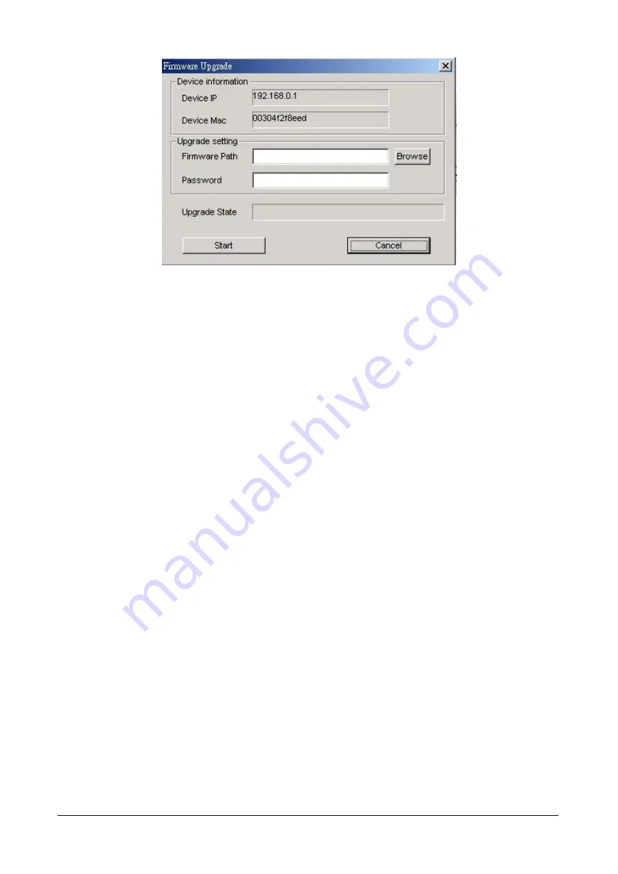
Figure 3-19 

Firmware Upgrade 

Web  Access: 

Double  click  the  device  in  the  Monitor  List  or  select  a  device  in  the  Monitor  List  and  press  this 

Web 

Access


button to access the Web interface of Switch.  

3.1.2 Configure the Switch 

The  Switch  Web  Smart  Gigabit  Ethernet  Switch  provide  Web  interface  for  Switch  smart  function  configuration.  The 
GSW-1600S /2400S can be configured through the Web Browser. A network administrator can manage and monitor the 
GSW-1600S /2400S from the local LAN. This section indicates how to configure the Switch to enable its smart function. 
The smart functions are shown as below: 


Port Setting (Speed/Disable, Duplex mode, Flow Control and Port base QoS) 


Virtual LAN Group setting (VLAN) 


Trunking 


Port Mirroring 


System Setting 


Device status and Statistic 


Trap and Password 


Backup Setting 

3.1.2.1

 Login the Switch 

Before you start configure the Switch, please note the Switch is configured through an Ethernet connection, make sure the 
manager  PC  must  be  set  on  same  the 

IP  subnet  address

.  For  example,  the  default  IP  address  of  the  Switch  is 

192.168.0.1

, then the manager PC should be set at 192.168.0.x (where x is a number between 2 and 254), and the default 

subnet mask is 255.255.255.0. Use Internet Explorer 5.0 or above Web browser. Enter IP address 

http://192.168.0.1 

(the 

factory-default IP address) to access the Web interface.  

Or through the Web Switch Utility, do not need to remember the IP Address, select the device in the Monitor List of the Web 
Switch Utility to settle the device through the Web Browser. When the following login screen appears, please enter the 
default password 

"admin" 

and press Login to enter the main screen of Switch. The login screen in Figure 3-20 appears. 

Summary of Contents for GSW-1600S

Page 1: ...10 100 1000Mbps 16 24 port Web Smart Gigabit Ethernet Switch GSW 1600S GSW 2400S User s Manual...

Page 2: ...improvements to this User s Manual and or to the products described in this User s Manual at any time without notice If you find information in this manual that is incorrect misleading or incomplete...

Page 3: ...1 4 GSW 1600S 2400S Rear Panel 4 2 2 INSTALLING A GSW 1600S 2400S 4 2 2 1 Desktop Installation 4 2 2 2 Rack Mounting 5 3 CONFIGURATION 7 3 1 PREPARING FOR CONFIGURATION 7 3 1 1 Install the Web Switch...

Page 4: ...GSW 1600S 2400S Appendices It contains cable information of GSW 1600S 2400S In the following section terms Switch with upper case means the two switches i e GSW 1600S or GSW 2400S Terms with lower cas...

Page 5: ...ffer 512KB 512KB Flow Control Back pressure for half duplex IEEE 802 3x Pause Frame for full duplex Dimensions mm 440 x 210 x 44 1U height Weight 2 83kg 2 93kg Power Requirement 100 240V AC 50 60 Hz P...

Page 6: ...orrect transmission speed and half full duplex mode of the attached devices with its 16 24 ports The Gigabit port can handle large amounts of data transmission in a secure topology linking to a backbo...

Page 7: ...gabit Ethernet Switch and make connections to the Switch Please read the following topics and perform the procedures in the order being presented PLANET Web Smart Gigabit Ethernet Switch do not need s...

Page 8: ...o attach brackets to one side of the switch Figure 2 5 Attaching the brackets to the GSW 2400S Caution You must use the screws supplied with the mounting brackets Damage caused to the parts by using i...

Page 9: ...6...

Page 10: ...or the Switch You can easily configure the Switch s Smart function through the Web browser Such as per port speed duplex flow control QoS settings Trunking and port based VLAN port mirroring 3 1 1 Ins...

Page 11: ...8 Figure 3 2 Web Switch Utility installation wizard Press on Next button to install the Web Switch Utility to the default installation folder Figure 3 3 Web Switch Utility installation process...

Page 12: ...9 Figure 3 4 Web Switch Utility installation process Figure 3 5 Web Switch Utility installation process...

Page 13: ...Web Switch Utility installation completed 3 After complete the installation run Web Switch Utility exe in default installation folder C Program Files Web Switch Utility or run start Program Files PLAN...

Page 14: ...e File View Option and Help 3 1 1 1 1 File The File function category contains Monitor Save Monitor Save As Monitor Load and Exit items The detail explanation of each item shows in the following Monit...

Page 15: ...each item is shown as below View Log to display the events of the Switch Clear Log to clear the log of Switch Figure 3 10 View TAB on Web Switch Utility 3 1 1 1 3 Option In the Option function categor...

Page 16: ...3 1 1 2 Discovery List This function allows user to list the Switch in the entire network By pressing the Discovery button you can list all the Switch in the discovery list Double click or press the...

Page 17: ...Trap IP display the IP address where the Trap to be sent Subnet Mask display the Subnet Mask set of Switch Gateway display the Gateway set of the Switch 3 1 1 3 Monitor List All the Switch in the Mon...

Page 18: ...trap function receives the events from Switch in the Monitor List A light indicator beside the View Trap button is to notice managers whether there are system events in the trap information box Green...

Page 19: ...this function is to assign IP Address Subnet Mask Gateway and Set Trap to Trap IP Address System name and Location Select one device in the Discovery list or Monitor List and press this button then t...

Page 20: ...e status and Statistic Trap and Password Backup Setting 3 1 2 1 Login the Switch Before you start configure the Switch please note the Switch is configured through an Ethernet connection make sure the...

Page 21: ...reen in Figure 3 21 appears Figure 3 21 The Main page 3 1 2 3 Port This function allows displaying each port s status The Link Status in the screen displays the current connection speed and duplex mod...

Page 22: ...e handling flow control Set Flow Control to enable for avoiding data transfer overflow Or it sets to disable there is either no flow control or other hardware software management When the port is set...

Page 23: ...tion screen will pop out you can fill in the description in order to describe this VLAN Group check on the port to be a member to this VLAN Group and press Apply button to take effect Once you want to...

Page 24: ...ction provide to monitoring network traffic that forwards a copy of each incoming or outgoing packet from one port of a network Switch to another port where the packet can be studied It enables the ma...

Page 25: ...ay the Switch Status Port Status VLAN Status Trunk Status and Mirror Status Press Refresh to renew the posted information The Status screen in Figure 3 28 appears Figure 3 28 Status page 3 1 2 8 Stati...

Page 26: ...Address Subnet Mask and Gateway Through the Web Switch Utility you can easily recognize the device by using the System Name and the Location Name The Login Timeout is to set the idle time out for sec...

Page 27: ...ption of each item is shown as below Events Monitoring the Switch s trap Device Bootup produce a trap when booting up the Switch Illegal Login produce a trap when there is a wrong password login and i...

Page 28: ...elease the Reset button in the rear panel of Switch the current setting includes VLAN will be lost and the Switch will restore to the default mode 3 1 2 12 Backup Setting This function allows backup t...

Page 29: ...26 Figure 3 35 Backup Setting dialog box Figure 3 36 Backup Setting dialog box Figure 3 37 Backup Setting message box...

Page 30: ...onfiguration The screen in Figure 3 38 3 39 appears Figure 3 38 Restore Setting page Figure 3 39 Restore Setting page 3 1 2 13 Reset Setting The Factory Reset button can reset the Switch back to the f...

Page 31: ...8 Figure 3 40 Reset Setting page 3 1 2 14 Logout Click on this link the web management interface logout immediately and login page appears Figure 3 41 Login page appears after click on the Logout link...

Page 32: ...complete error checking before transmission Therefore no error packets occurrence it is the best choice when a network needs efficiency and stability The Ethernet Switch scans the destination address...

Page 33: ...I_DB BI_DA 4 BI_DC BI_DD 5 BI_DC BI_DD 6 BI_DB BI_DA 7 BI_DD BI_DC 8 BI_DD BI_DC Implicit implementation of the crossover function within a twisted pair cable or at a wiring panel while not expressly...

Reviews: