background image

Chapter 2 Display Controls 


User Controls 

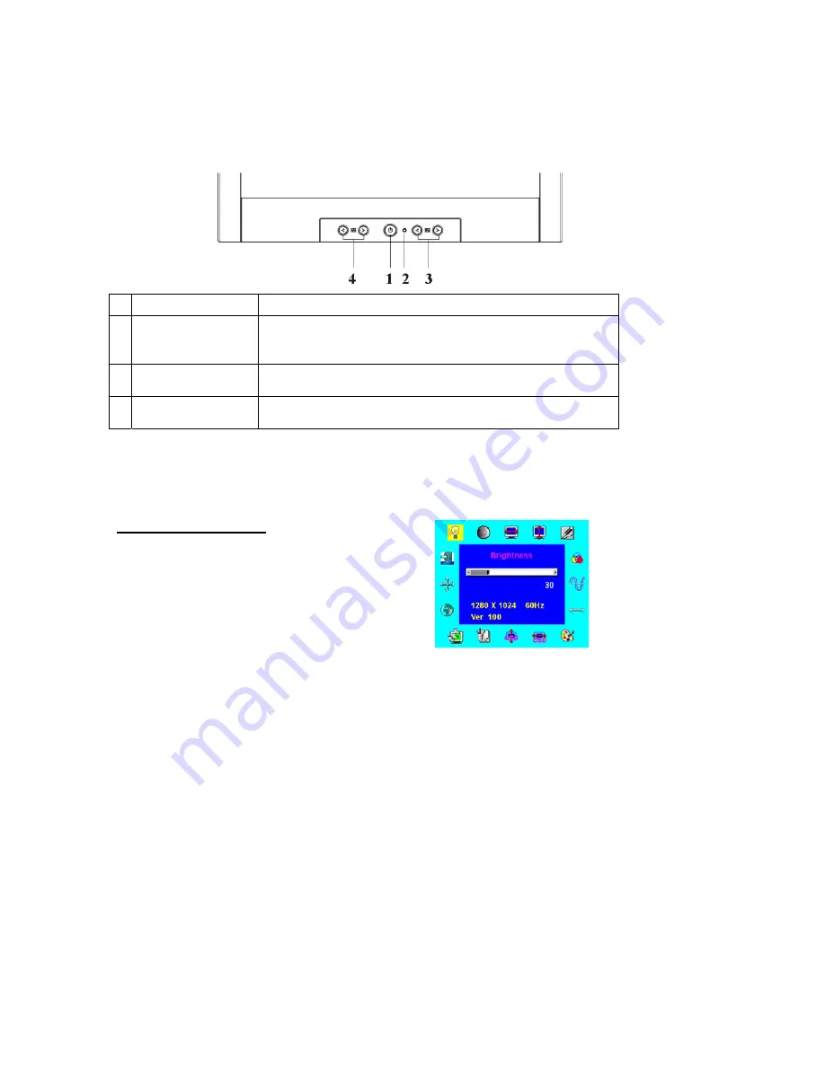
A brief description and the location of all LCD Monitor function controls and indicators: 

Figure 2-1


DC Power Switch


Press the power switch to switch the monitor ON/OFF. 

DC Power-On 
Indicator


LED lights Green color --- Power is ON.   
LED lights Yellow --- Monitor is in "Power Saving Mode". 
LED is off --- Power is OFF. 

Function Select 
Buttons


Press either left or right control button for OSD (On Screen 
Display) menu selection. 

Adjustment 
Control Buttons


Press the left button to decrease the OSD setting and press the 
right button to increase the OSD setting. 

Adjusting the Monitor's Display 

The monitor has four function control buttons to select among functions shown on OSD menu, designed for 
easy user-viewing environments. 

OSD Function Menu


To access OSD Main menu, simply press one of the 
Function Select control buttons, and the menu diagram 
will pop up on the screen as shown on Fig. 2-2: 
Continue pressing the Function Select buttons to scroll 
through the entire menu items ,then press Adjustment 
Control buttons to adjust content of selected item. 


Figure 2-2


Attention 

Firmware revision may have been updated into a latest version while the version number shown on all OSD menus in 

this manual will stay as Ver. 1.00. 


5

Summary of Contents for PE170

Page 1: ...PLANAR LCD MONITOR PE170 MANUAL www planar com ...

Page 2: ...D Monitor from Its Stand 3 Interface for Arm Applications 3 Connecting the Display 4 Connecting the AC Power 4 Setting Up the LCD Monitor 4 Power Management System 4 Chapter 2 Display Controls 5 User Controls 5 Adjusting the Monitor s Display 5 Function Description 6 Chapter 3 Technical Information 8 Specifications 8 Standard Timing Table 10 Troubleshooting 10 1 ...

Page 3: ...ications not expressly approved by the manufacturers may void the user s authority to operate this equipment NOTE A shielded type signal cord is required in order to meet the FCC emission limits and also to prevent interference to the radio and television reception It is essential that only the supplied signal cord be used Canadian DOC Notice This Class B digital apparatus meets all requirements o...

Page 4: ...st Then connect the LCD Monitor and base please See fig 1 1 Figure 1 1 Viewing Angle Adjustment The LCD Monitor is designed to allow users to have a comfortable viewing angle The viewing angle can be adjusted from 5 to 30 See fig 1 2 Figure 1 2 Warning Do not force the LCD Monitor over its maximum viewing angle settings as stated above Attempting this will result in damaging the Monitor and Monito...

Page 5: ...te core video cable is used Connecting the AC Power 1 Connect the power cord to the LCD Monitor See Fig 1 6 2 Connect the power cord to an AC power source Figure 1 6 Setting Up the LCD Monitor 1 Turn on the LCD monitor s hard power switch located on the back of the monitor 2 Turn on the LCD Monitor s soft power switch located on the bezel of the monitor Figure 1 7 Power Management System This LCD ...

Page 6: ...D setting and press the right button to increase the OSD setting Adjusting the Monitor s Display The monitor has four function control buttons to select among functions shown on OSD menu designed for easy user viewing environments OSD Function Menu To access OSD Main menu simply press one of the Function Select control buttons and the menu diagram will pop up on the screen as shown on Fig 2 2 Cont...

Page 7: ... input timing and supported timing The clock value may not be 0 after Auto Adjustment when the input timing is different from supported timing Color Temperature Push the button to select a different color temperature Please see the diagram below for function and description OSD H Position This function moves the OSD menu window horizontally OSD V Position This function moves the OSD menu window ve...

Page 8: ...K 7500 CIE coordinated Color Temperature of 7500 K Sets the CIE coordinate color temperature to 7500 K 6500 CIE coordinated Color Temperature of 6500 K Sets the CIE coordinate color temperature to 6500 K User Three colors Red Green Blue can be adjusted from the OSD menu Sets the settings to a by user defined CIE Temperature 7 ...

Page 9: ...nal Input Impedance Polarity Amplitude Multi mode Supported Analog RGB 0 7Vp p 75 Ohm 2 Positive Negative 0 0 7 0 05 Vp Horizontal Frequency 24 80 KHz Vertical Frequency 56 75 Hz Control Power switch hard and soft types On Off switch with LED indicator Power Management Mode Power Consumption AC Input LED Color On 48W maximum 240 VAC Green Off 3W maximum 240 VAC Yellow Soft switch off 3W maximum 24...

Page 10: ...re 20 C to 60 C 4 F to140 F Relative 5 to 85 Power Supply AC Input Input Voltage Single phase 100 240VAC 50 60 Hz Input Current 1 2 A maximum Size and Weight Dimensions 374 W x 394 5 H x 204 D mm Net Weight 5 0 3 kg Gross Weight 7 0 3 kg Pin Assignment Signal Signal PIN Description PIN Description 1 5 6 10 11 15 1 2 3 4 5 6 7 8 Red Green Blue Digital GND Digital GND Red Rtn Green Rtn Blue Rtn 9 10...

Page 11: ...pports Multiple VGA Modes Refer to the Standard Timing Table for a listing of modes supported by this LCD Monitor PROBLEM Picture is unclear and unstable The picture is unclear and unstable please perform the following steps 1 Enter PC to Shut Down Windows status while you re in MS Windows environment 2 Check the screen to see if there s any black vertical stripes appear If there are take advantag...

Page 12: ...271 Hours M F 8am 9pm Eastern Time 2003 Planar Systems Inc 05 03 Planar is a registered trademark of Planar Systems Inc Other brands and names are the property of their respective owners Technical information in this document is subject to change without notice Online Support http planar custhelp com ...

Reviews: