


Connecting the Matrix Video Extender Box
8
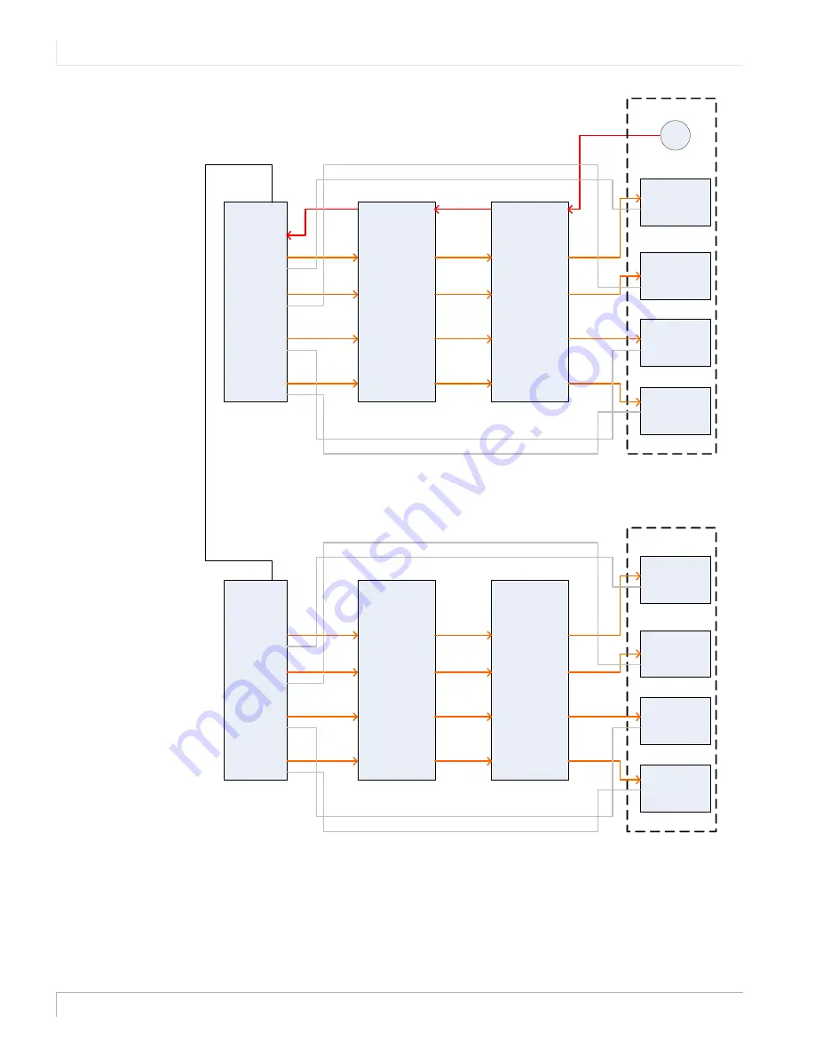
Note:
The COMM cables do not run through the extender box, as it is not necessary to
boost them along the way.
The equalization settings are linked to the INPUT side of the extender box. For
different cable lengths, see "EQ Settings Per Cable Length" on page 5.
Quad Module 1
IR
VIDEO 1
COMM 1
VIDEO 2
COMM 2
VIDEO 3
COMM 3
VIDEO 4
COMM 4
RS485
Extender Box
IR Out
IR In
1
2
3
4
LCD In
LCD Out
1
2
3
4
Extender Box
IR Out
IR In
1
2
3
4
LCD In
LCD Out
1
2
3
4
Vi
deo
W
a
ll
VIDEO
COMM
VIDEO
COMM
VIDEO
COMM
LCD 1
LCD 2
LCD 3
LCD 4
IR sensor
VIDEO
COMM
Quad Module 2
IR
VIDEO 1
COMM 1
VIDEO 2
COMM 2
VIDEO 3
COMM 3
VIDEO 4
COMM 4
RS485
Extender Box
IR Out
IR In
1
2
3
4
LCD In
LCD Out
1
2
3
4
Extender Box
IR Out
IR In
1
2
3
4
LCD In
LCD Out
1
2
3
4
Vide
o Wa
ll
VIDEO
COMM
VIDEO
COMM
VIDEO
COMM
LCD 1
LCD 2
LCD 3
LCD 4
VIDEO
COMM


