background image


EL480.240-PR2/PR3 Users Manual 

10 

Self-Test Mode 

The display incorporates a self-test mode composed of two patterns displayed 
for approximately 30 seconds each, and then repeated. The patterns are as 
follows: Diagonal Lines, Diagonal Lines Inverted, Full On,  1 x 1 Checkerboard, 
and 1 x 1 Checkerboard Inverted. The self-test mode is entered by resetting or 
applying power to the display with the VCLK signal static. The display will 
remain in the self-test mode until two edges of VCLK are detected. 

Optical 

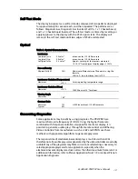
Table 5. Optical Characteristics. 

Luminance 
Lon (areal), min 
Lon (areal), typ 
Loff (pixel), max 

30 cd/m

²


50 cd/m

²


0.3 cd/m

²


screen center, 120 Hz frame rate 
5 points: center plus four corners measured  
1.0 

r

0.25" from adjacent display edges, 120 Hz 

Non-uniformity 
All pixels fully lit 

26% 

Maximum difference two of five points, using the 
formula: 
LNU%=[1- (min_lum/max_lum)] x 100 

Luminance Variation (Temperature) 
Maximum 

r

15% 

Across operating temperature range 

Luminance Variation (Time) 
Maximum 

<10% 

15,000 hours at 25

q

C ambient 

Viewing Angle 
Minimum 

160

q


Contrast Ratio 
Minimum 
Typical 

19:1 
50:1 

@ 500 lux ambient, 120 Hz frame rate 

Generating Grayscales 

Some applications may benefit by using grayscales. The PR2/PR3 has a 
maximum frame rate frequency of 120 Hz. Using the higher frame rate, 
combined with flat panel controllers designed for this faster display, it is 
possible to generate usable grays through frame rate control and dithering. 
Video controllers from manufacturers such as C&T and EPSON use these 
methods with proprietary algorithms to generate grayscales.   

The response time of electroluminescent displays is much faster than LCDs, 
therefore not all possible grayscales generated by the video controller are actually 
usable. Many of the grayscales may flicker or swim. Careful testing is necessary to 
select appropriate grayscales for an application, especially when the 
electroluminescent displays are driven at less than their maximum frame rate. For 
additional information, refer to Planar Application Note 119 or contact Planar's 
Application Engineers. 

Summary of Contents for ICEBrite EL480.240-PR2

Page 1: ...EL480 240 PR2 PR3 Users Manual 1 EL480 240 PR2 PR3 ICEBrite Small Graphics Display USER S MANUAL www planar com...

Page 2: ...chanical Characteristics 12 Component Envelope 12 Description of Warranty 14 Ordering Information 14 Support and Service 15 Figures Figure 1 Power supply and logic signal sequencing requirement 6 Figu...

Page 3: ...g rugged package for easy mounting The EL480 240 PR2 PR3 is easily interfaced using standard 4 bit LCD control signals Each of the 115 200 pixels has an aspect ratio of 1 1 V H and is individually add...

Page 4: ...ve loads Stresses are often introduced when a display is mounted into a product Ideally the mounting tabs of the display should be the only point of contact with the system Use a spacer or boss for su...

Page 5: ...n Cleaning As with any glass or coated surface care should be taken to minimize scratching Clean the display glass with mild water based detergents only Apply the cleaner sparingly to a soft cloth the...

Page 6: ...pply voltage VH The logic supply voltage VL should be present whenever video input signals or VH is applied The minimum and maximum specifications in this manual should be met without exception to ens...

Page 7: ...nector Video signals and DC power are connected to the display through a dual row 0 050 inch square pin connector AMP part number 104549 2 For flexible cable connection to the display use AMP part num...

Page 8: ...t LCD type video interface provides a low cost flexible method for controlling display brightness and power consumption Video Input Signals The end of the top line of a frame is marked by VS vertical...

Page 9: ...VCLKh 15 70 nsec 9 VS high setup to HS low tVShsu 140 nsec 10 VS hold after HS tVShd 140 nsec 11 VS low setup to HS high tVSlsu 140 nsec 12 HS period tHS 34 sec VS period tVS 242 tHS Frame Rate fVS 50...

Page 10: ...cross operating temperature range Luminance Variation Time Maximum 10 15 000 hours at 25qC ambient Viewing Angle Minimum 160q Contrast Ratio Minimum Typical 19 1 50 1 500 lux ambient 120 Hz frame rate...

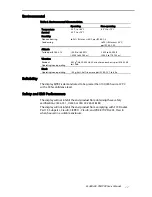
Page 11: ...operating 0 02g2 Hz 20 500 Hz 30 minutes on each axis per IEC 68 2 36 test Fdb Shock Operating non operating 100 g 6 ms half sine wave per IEC 68 2 27 test Ea Reliability The display MTBF is demonstra...

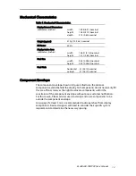
Page 12: ...31 0 012 nominal vertical 31 0 012 nominal Component Envelope The component envelope shown in Figure 4 illustrates the distance components extend behind the display Tall components do not necessarily...

Page 13: ...R2 PR3 Users Manual 13 Figure 4 Display Dimensions Note The dimensions in this drawing are approximate Please contact Planar Applications Engineering and request the actual drawing prior to beginning...

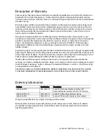
Page 14: ...other liability to Buyer All warranty repairs must be performed at Seller s authorized service center using parts approved by Seller Buyer shall pay costs of sending Goods to Seller on a warranty cla...

Page 15: ...port and service are available to make the integration of Planar displays as simple and quick as possible for our customers RMA Procedure For a Returned Material Authorization number please contact Pl...

Page 16: ...ope and Asia Pacific Support Olarinluoma 9 P O Box 46 FIN 02201 Espoo Finland Tel 358 9 420 01 Hours M F 7 00am 4pm CET 2004 Planar Systems Inc 06 04 Planar is a registered trademark of Planar Systems...

Reviews: