background image


EL640.480-AM Operations Manual (020-0351-00C) 

13 

Optical Performance 

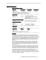
Table 6. Optical Characteristics. 

Luminance 

L

on

 (areal), min 

L

on

 (areal), typ 

L

off

 (areal), max 

AM1 
AM8 IN/ET/ETL 

40 cd/m² 
35 cd/m² 

65 cd/m² 
49 cd/m² 

0.3 cd/m² 
0.3 cd/m² 

Minimum and Typical: Center, 120 Hz frame rate 
Maximum: Center and four corners, 120 Hz frame rate 

Non-uniformity 

AM1 
AM8 IN/ET/ETL 

35% 
26% 

All pixels fully on @120 Hz 
Maximum difference two of five points, 
using the formula: 
BNU%=[1- (min_lum/max_lum)] x 100% 

Luminance Variation (Temperature) 

Maximum 

15% 

Across operating temperature range 

Luminance Variation (Time)


Maximum 
AM1 
AM8 IN/ET/ETL 


20% 
10% 

 
10,000 hours at 25

°

C ambient 

10,000 hours at 25

°

C ambient 

Viewing Angle 

Minimum 

  160

°


Contrast Ratio 

Minimum 

Typical 


AM1 
AM8 IN/ET/ETL 

19:1 
35:1  

40:1 
70:1 


Minimum: @ 500 lux ambient, @ 120 Hz frame rate 

Dimming 

There are two standard methods for dimming the AM displays. Frame rate 
dimming allows the brightness of the display to be lowered proportionally by 
reducing the frame rate. Analog dimming allows the brightness to be reduced 
with an external, user supplied potentiometer or electronic circuitry. The 
brightness range for analog dimming is from 100% to nearly 5% of the full 
brightness. 

Frame rate dimming is performed within the application by lowering the 
frame rate of the video input signals. Because brightness is proportional to 
refresh rate, the display can be dimmed by adding pauses between every 
horizontal period. 

The lowest possible frame rate (brightness) is dependent on the perceived 
flicker of the displayed image, but will most likely be around 60 Hz. For more 
information on frame rate dimming please see Planar Application Note 120. 

The analog dimming feature utilizes a 50k ohm logarithmic external 
potentiometer, allowing manual control of the display’s brightness. Analog 
dimming is standard on the AM8 IN and AM8 ET displays. The typical current 
for minimum brightness is 220 µA. 

Summary of Contents for ICEBrite EL VGA Displays EL640.480-AM

Page 1: ...EL640 480 AM Series ICEBrite EL VGA Displays USER S MANUAL www planar com...

Page 2: ......

Page 3: ...nnectors 7 AM1 Data and Power Connector 7 AM8 Data and Power Connector 8 Locking Power and Data Connector 9 Dimming Connector J2 9 Interfacing 9 Video Input Signals 10 Self Test Mode 12 Optical Perfor...

Page 4: ...agram 11 Figure 5 Data Format 12 Figure 6 AM Series Dimensions 16 Tables Table 1 DC Input Voltage Requirements 6 Table 2 Video Input Requirements 6 Table 3 J1 Connector Pinouts 8 Table 4 Video Input T...

Page 5: ...these displays excel in ambient light environments ranging from dark rooms to nearly sunlight This proprietary technology achieves very high contrast and exceptionally clear images These displays are...

Page 6: ...ts Do not drop bend or flex the display Do not allow objects to strike the surface of the display Mounting EL Displays The EL640 480 AM displays were designed to facilitate the mounting of optical tre...

Page 7: ...ents only Apply the cleaner sparingly to a soft cloth then wipe the display Disposable cleaning cloths are recommended to minimize the risk of inadvertently scratching the display with particles embed...

Page 8: ...Table 1 DC Input Voltage Requirements AM1 AM8 ETL AM8 IN ET Notes 12 V 24 V VL 5 V 5 5 V 5 5 V 5 absolute max 7 0 V VH 12 V 10 12 V 10 24 V 10 absolute max 15 V and 30 V respectively IL max 75 mA 75 m...

Page 9: ...the jumper in the desired position in environments where shock or vibration might loosen the jumper The minimum and maximum specifications in the manual should be met without exception to ensure the l...

Page 10: ...ntative 1 800 SAMTEC9 for the cable connector options Figure 2 AM8 Data Power Connector Table 3 J1 Connector Pinouts Pin Signal Description Pin Signal Description 1 UD1 Video data upper 2 UD0 Video da...

Page 11: ...ting connector is a Molex 22 01 3027 housing and 08 52 0123 crimps 2 per housing Additionally the crimp housing will need crimp terminals to connect the wires Molex 2759 or 6459 can be used Molex crim...

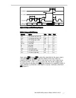
Page 12: ...n in Figure 3 and Figure 4 S FRAME CP1 LINE UD0 to UD3 LD0 to LD3 frame n 1 frame n frame n 1 row 240 480 row 1 241 row 1 241 160 CP2 pulses CP1 L INE UD0 to UD3 LD0 to LD3 First pixels 1 4 Last pixel...

Page 13: ...tR Rise time 30 ns tF Fall time 30 ns tCLK CP2 clock cycle 154 ns tCL CP2 clock low time 60 ns tCH CP2 clock high time 60 ns Input signals UD0 through UD3 contain the video data for the upper screen a...

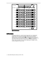
Page 14: ...5 Data Format Self Test Mode The display incorporates a self test mode composed of a 1x2 checkerboard pattern that inverts every few seconds The self test mode is entered by applying power to the disp...

Page 15: ...ing the AM displays Frame rate dimming allows the brightness of the display to be lowered proportionally by reducing the frame rate Analog dimming allows the brightness to be reduced with an external...

Page 16: ...ered grayscales When the area is viewed from a distance it appears to the user s eye as gray When viewed up close the different brightness of the individual pixels can be observed Many of the grayscal...

Page 17: ...tude AM1 AM8 Operating 0 to 5 km 16k ft 0 to 18 km 58k ft Non Operating 0 to 18 km 58k ft per IEC 68 2 13 Vibration Random 0 02 g Hz ASD level 20 500 Hz per IEC 68 2 36 test Fdb Shock Half sine wave 1...

Page 18: ...essarily fill this area Planar reserves the right to relocate components within the constraints of the component s envelope without prior customer notification For this reason Planar advises users to...

Page 19: ...stall operate handle or maintain the Goods are not within this warranty Repair or replacement of Goods is Seller s sole obligation and Buyer s exclusive remedy for all claims of defects If that remedy...

Page 20: ...ing low profile locking data and power connector EL640 480 AM8 ETL CC 996 0268 29LF EL640 480 AM8 ETL with conformal coating Design and specifications are subject to change without notice Planar Syste...

Page 21: ...ope and Asia Pacific Support Olarinluoma 9 P O Box 46 FIN 02201 Espoo Finland Tel 358 9 420 01 Hours M F 7 00am 4pm CET 2004 Planar Systems Inc 06 04 Planar is a registered trademark of Planar Systems...

Reviews: