background image


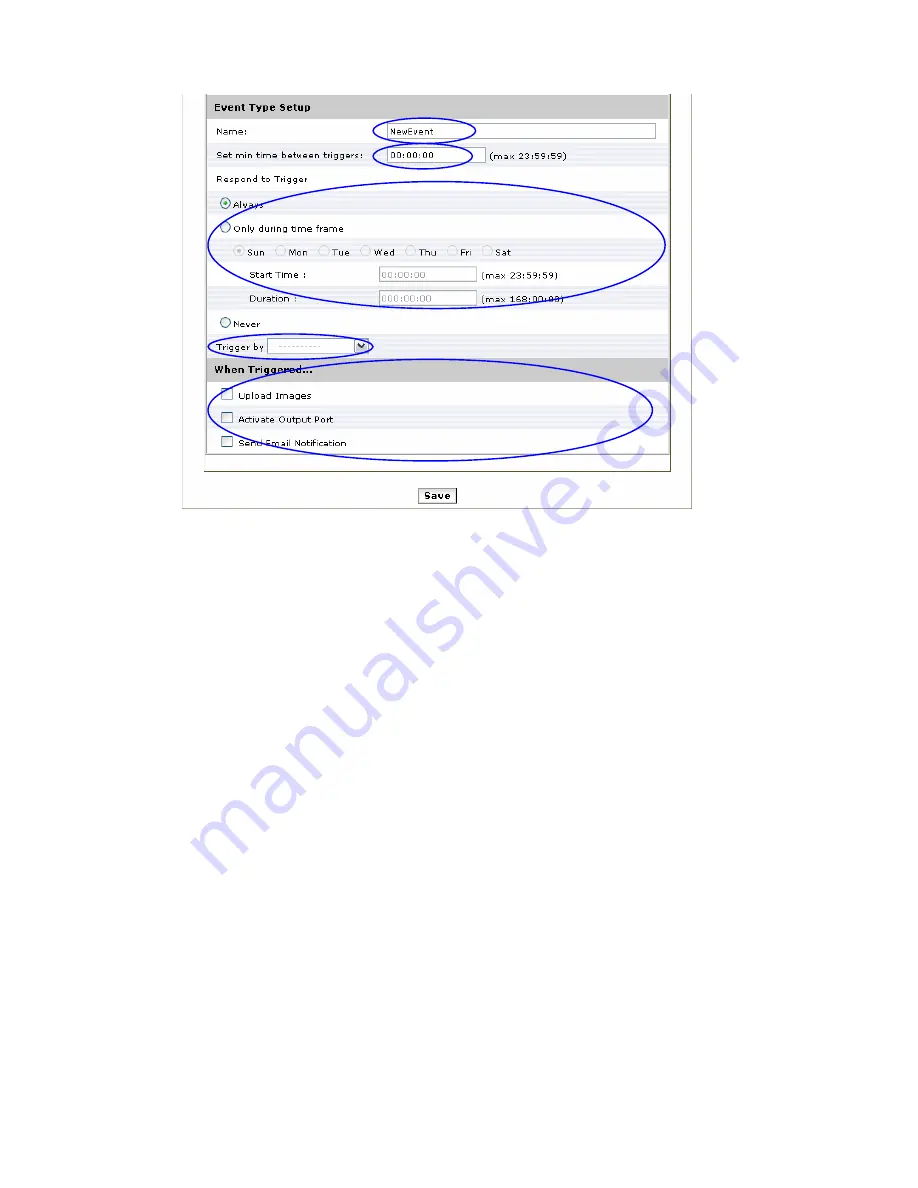
2. Give a name to this event. 

3. Set the time interval between each trigger 

4. Set the time period for the trigger. Choose “Always”, “During time frame” or “Never” 

During time frame: Choose a day and the starting time then configure the duration time (168hrs = 24x7). 

For example if duration time is set to 168(hrs), it is the same as choosing “Always”   

5. Choose the triggering condition, “GPIN”, “Manual trigger”, “Motion detection” and “On boot” 

6. Choose the triggered event. “Upload images”, “Active Output port”, “Send email notification” 

7. Finally click on 

[Save]

 to save the configuration made. 


25

Summary of Contents for PL621

Page 1: ...PiXORD H 264 Series 2 Megapixel Network Camera PL621 PL621E User s Manual Version 1 0 Date 09 04 2010...

Page 2: ...4 Event 19 Event Server 19 Motion Detection 21 I O Ports 23 Event Configuration 24 5 Schedule 26 General 26 Storage 27 6 Network 28 General 28 Advanced 29 SMTP E Mail 31 DDNS 32 7 System 33 Informati...

Page 3: ...sive strike Do not install the equipment near any flames or heat sources Excessive heat could damage this equipment Do not cover cloth or to install this equipment in poorly ventilated places Overheat...

Page 4: ...where a failure of the PiXORD product would cause severe personal injury or death unless officers of the parties have executed an agreement specifically governing such use Reproduction of PiXORD info...

Page 5: ...quality Motion JPEG is supported for increased flexibility as well as multiple independent video streaming PL621 value added features include on board video motion detection SD slot for storage record...

Page 6: ...rnet link to the network 2 Connect LAN port RJ45 of the camera to a network switch hub 3 Connect power jack 4 Ensure the power adaptor specification matches the power system 110V or 220V and connect t...

Page 7: ...twork settings of the device or for finding a device once the network settings have been modified To install the IP Installer from the Software Package CD UI select IP installer then follow the on scr...

Page 8: ...3 MAC Address Each device has a unique Ethernet address MAC address shown on the label of the device as the serial number S N with 12 digits e g 000429 XXXXXX 7 0004290000 4 Although the IP Installer...

Page 9: ...it s S N Serial Number 4 Double click the item to open the Property Page for the selected device or click the menu bar View Property 5 After filling in the properties click Set button to complete the...

Page 10: ...When browsing the Home Page at the first time with the Microsoft Internet Explorer TM you must temporarily lower your security settings to perform a one time only installation of the ActiveX componen...

Page 11: ...Using the Web UI Start your Web browser and enter the URL or IP address in the Address field The Home page of the camera is now displayed 10...

Page 12: ...ect languages among English traditional Chinese and simplify Chinese Check actual size to view the actual size resolution of the image Click to trigger the alarm manually Choose among the 3 streams fo...

Page 13: ...Button Description Full screen Listen the audio input from local end Talk function Record instant live video Snapshot the image Rotate image 90 degrees clockwise 12...

Page 14: ...l Video Source Camera General Advance Event Event Server Motion Detection I O Ports Event Configuration Schedule General Storage Network General Advance SMTP E mail DDNS System Information User Date T...

Page 15: ...eneral Video General Setting Check each box to enable streams max 3 for live viewing Note Digital PTZ is only available with stream 2 OSD Setting Enable OSD to display camera name and date time on the...

Page 16: ...rget bit rate range from 64 to 6000kb Image Format 2 kinds of format to choose from MJPEG and H 264 GOP Group of pictures Frame Rates FPS Choose the number of frames to display per second With resolut...

Page 17: ...3 Camera General 16...

Page 18: ...ble Turn on off the audio Web Record Setting Save Path File name Click on the Browse button to select the desired path to save as well as naming the video file Web Snapshot Image Setting Save Path Fil...

Page 19: ...educe the exposure time for lens Max Gain Control image at low light control on how much noises are allowed Infrared IR Cut Filter IR will activate depending on the light sensor it is for better visio...

Page 20: ...P to expand FTP server setting 19 FTP Server Name Give a name for the FTP server Network Address Input the network address of the FTP server Upload Path Choose the desired upload path for events Port...

Page 21: ...Login Information Username Password Input the username and password of the FTP Click Remove to delete selected event servers circled in red 20...

Page 22: ...Motion Detection 1 To add a motion detection area 1 Click on Add to set up a detection area Set up panel will be expanded 21...

Page 23: ...area 3 Select the trigger level and sensitivity for this detection window 0 100 low high 4 Select color for detection window 5 Draw detection window on the image 6 Once everything is done click on Sav...

Page 24: ...on list circle in blue Note Maximum number of detection window is 10 I O Ports Input Ports Setting 1 and 2 Name The name of Digital Input1 2 Current State Current Input state Output Ports Setting Name...

Page 25: ...Event Configuration 1 To add an event trigger click on Add and setup panel will be expanded 24...

Page 26: ...se a day and the starting time then configure the duration time 168hrs 24x7 For example if duration time is set to 168 hrs it is the same as choosing Always 5 Choose the triggering condition GPIN Manu...

Page 27: ...that will be recording during the scheduled period Note that only video data will be recorded User can select which video stream should be recorded and the size of each sliced file When the check box...

Page 28: ...e information includes disk size info type and status The warning message shows when recording is on process SD card should not be removed during the recording process It is the best to format the dis...

Page 29: ...and PPPoE Enable ARP Ping enable device to accept ARP or ping packets from the network Disable this option may provide extra security from intentional ping After all settings are made please reboot th...

Page 30: ...ess RTSP set the RTSP Video port for video data transmission HTTPS Enable Disable Http security function Bonjour Enable Bonjour service so that the device can be discovered with Bonjour service applie...

Page 31: ...30...

Page 32: ...f of the configured email account in a circumstance like sending an email notice to a specified mail address Event Configuration Sender Complete the Mail Server Server Port Authentication information...

Page 33: ...ce Internet access required Host Name Assigned name that will be used for access to the device User Name Password Account authentication for logging to this service Update Time Periodically the device...

Page 34: ...7 System Information Lists of System and Network configurations 33...

Page 35: ...s authentication required The Check box is for anonymous logging on to the live view page Logging for further configurations will still require user name and password Follow the conditions shown to ad...

Page 36: ...Date Time System date time configuration Options of synchronizing with PC and NTP server are provided for automatic adjustment 35...

Page 37: ...er Maintenance This page provides tool for system maintenance Reboot and Load default settings as well as functionalities of launching upgrade process backup restore user settings and language defines...

Page 38: ...Log Service Most system operations and or process will be kept in a log system The link provides the review of these records 37...

Page 39: ...two types of layout settings use default look or use custom settings Use Default Look the default layout of live configuration pages Use Defined Links Web link s will be presented on the live page wh...

Page 40: ...Use Custom Settings The modifications allowed are change of Background Text Color Background picture Title Description Logo and etc 39...

Page 41: ...ff the camera 2 Short pin 5 and pin 6 with a wire 3 Plug in the power jack to turn on the camera The power LED will start flashing in a short while 4 Break the short when the LED starts quick flashing...

Reviews: