background image

10


The Microvolt 3900 is a patchable, analog synthesizer. It combines the functionality of 11 individual synthesizer 
sections. The sections are internally connected to create a fully functional signal path without the need for patch 
cables, however 39 patch points are available to connect different synthesizer sections using 

1/8” 

mono patch 

cables to create custom sounds and textures. 


The Microvolt 3900 signal path is divided into two basic types of signals: audio signals and control voltages.


The audio signal carries the sound that is produced through the synthesizer. The audio signal path starts at the 
voltage controlled oscillator before passing through other synthesizer sections used to shape the sound such a 
mixer, filter, and VCA. Audio signal levels vary depending on their location in the signal path. This allows each 
synthesizer section to have the perfect signal level for the desired sonic results. Detailed information on each 
section can be found later in the manual.


Control voltages (CV) is a static or variable DC or AC voltage used to indirectly manipulate the audio signal by 
controlling the circuitry that processes the audio. This can be done using a few different types of CV. Gates are 
represented by a high or low control voltage to create a binary on or off state. A gate can be generated using a 
pulse or square wave from an oscillator or modulation source, or by using the gate or clock output from the midi 
module. A gate can be shaped using the function generator or envelope generator to create more complex 
control voltage (CV) signals. A gate signal or CV signal can be patched to any CV input on the Microvolt 3900 to 
be used as a modulation source. For example, a CV signal from the output of the function generator patched into 
the FM input of the oscillator section controls the frequency of oscillator based on the current state of the function 
generator.


Don

t forget, audio signals can be used as a control voltage source too. Audio rate modulation is always an 

interesting world to explore.


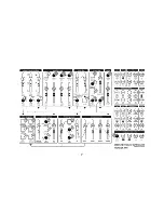
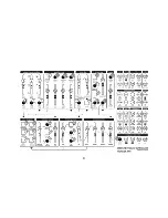
3. Microvolt 3900 Connections and Signals


Summary of Contents for Microvolt 3900

Page 1: ...pittsburgh modular synthesizers microvolt 3900 manual...

Page 2: ...2...

Page 3: ...uid design to create an instrument that does not need to fit the modern monosynth mold instead it allows us to experiment with new analog circuit designs and synthesis ideas The Microvolt 3900 is the...

Page 4: ...l cause the Microvolt 3900 circuitry to short circuit and may cause permanent damage Do not attempt to modify the Microvolt 3900 Tampering with the circuitry may cause permanent damage Do not place he...

Page 5: ...Synthesis Sections 18 8 Voltage Controlled Oscillator Waveform Generator 21 9 Waveform Mixer 22 10 Binary Filter 25 11 Dynamic VCA 26 12 Output 29 13 Midi Arpeggiator 30 14 Modulation Sources 42 16 F...

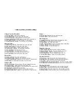
Page 6: ...ut Balance Trimmer Dynamic VCA inputs balance control 24 Dynamics Modulation Trimmer Set the dynamics CV input amount Output 25 Output Drive Trimmer Set the output drive gain 26 Output Slider Adjust t...

Page 7: ...7...

Page 8: ...8...

Page 9: ...el slider fold wave output Envelope 118 Input Jack Gate input used to trigger the envelope 119 Output Jack 0 5v shaped CV signal Filter 120 Frequency Input Jack Frequency modulation CV input 121 Input...

Page 10: ...on on each section can be found later in the manual Control voltages CV is a static or variable DC or AC voltage used to indirectly manipulate the audio signal by controlling the circuitry that proces...

Page 11: ...11...

Page 12: ...12...

Page 13: ...f CV trimmers An attenuator trimmer starts at zero signal when turned full left and at full right it is outputting the full signal level The zero point for an attenuverter trimmer is at 12 o clock Tur...

Page 14: ...to be cut when a patch cable is inserted A simple example would be the pitch input of the voltage controlled oscillator Internally the pitch output of the midi section is wired to the switched jack in...

Page 15: ...15...

Page 16: ...16...

Page 17: ...d Waveform Mixer Output Output of the Waveform Mixer sent to the input of the Binary Filter 121 e Function Generator Output Output of the Function Generator 134 sent to the Frequency Modulation Trimme...

Page 18: ...Synthesis Sections The Microvolt 3900 is comprised of 10 individual synthesis sections Each section has a corresponding set of jacks in the patch bay The following pages will explain the features of...

Page 19: ...19...

Page 20: ...20...

Page 21: ...itch input uses the 1 volt per octave standard for stable pitch tracking The pitch input is internally patched to the midi pitch output This allows the octave up 31 and octave down 32 buttons to be us...

Page 22: ...waveform level siders set the output level of the oscillator waveforms The output of each waveform level slider is patched internally to the input of the binary filter using switched jacks Patching i...

Page 23: ...23...

Page 24: ...24...

Page 25: ...e The frequency slider 15 sets the cutoff frequency of the low pass filter The resonance slider 16 adjusts the filter Q factor Patching into the filter frequency input 120 will break the connection wi...

Page 26: ...ard VCA The original lowpass gate was limited to a static response time that varied from unit to unit This made each lowpass gate a little different The dynamic VCA in the Microvolt 3900 adds a unique...

Page 27: ...27...

Page 28: ...28...

Page 29: ...verdrive circuit The output fader controls the level for both the line output 108 and headphone output 109 jacks The output of the dynamic vca is internally wired to the output section This can not be...

Page 30: ...nnel of the Microvolt 3900 is set to omni allowing the synthesizer to respond to all midi channels The midi input jack 105 uses the supplied stereo 1 8 to 5 pin din connector to connect to a tradition...

Page 31: ...31...

Page 32: ...32...

Page 33: ...urorack standard 1 volt per octave scaled CV is output from the pitch jack 104 The gate output jack 106 outputs a high signal 5v when a key is pressed The gate output jack outputs a low signal 0v when...

Page 34: ...hold keys on a midi keyboard The arpeggiator will cycle through the depressed keys in the order they were pressed sometimes called as played To stop the arpeggiated sequence release one or all of the...

Page 35: ...35...

Page 36: ...36...

Page 37: ...ing and holding the edit button 30 then pressing the arpeggiator button 27 The random function will random jump between the notes of the arpeggiated sequence Disable random by pressing and holding the...

Page 38: ...is saved in memory and recalled when the Microvolt 3900 is powered on External Midi Clock The external midi clock responds to midi start stop messages and midi tempo from an external midi clock source...

Page 39: ...39...

Page 40: ...40...

Page 41: ...the Microvolt 3900 is powered on Midi Channel The Microvolt 3900 can be assigned to midi channel 1 16 or omni To set the midi channel press and hold the edit button 30 The midi can only be changed wh...

Page 42: ...ps to the next step there is a chance the value stored in that step will be replaced with a new value The result is a random source that feels both random and evolutionary with an ever evolving 6 step...

Page 43: ...43...

Page 44: ...44...

Page 45: ...er offset section to the input of the function generator 133 and the second output jack 138 into the input of the envelope generator 118 Use the Random CV output jack as a modulation source for the fu...

Page 46: ...midi gate jack 106 If you do not want the midi gate to trigger the function generator plug a patch cable in the input jack 133 of the function generator to break the internal connection to the midi ga...

Page 47: ...47...

Page 48: ...48...

Page 49: ...ime needed for the envelope generator to reach the peak output voltage and move on to the decay stage The decay slider 42 sets the amount of time needed to transition to the level set by the sustain s...

Page 50: ...f an inverted version of the signal up to the level of the incoming signal or unity gain Signal Splitter Patch a signal into input a the turn the input a level trimmer 45 full right A copy of the inpu...

Page 51: ...51...

Page 52: ...amples that showcase the wide range of functionality and sounds available using only the Microvolt 3900 and a midi keyboard The patches are designed to familiarize musicians with the layout synthesis...

Page 53: ...53...

Page 54: ...54...

Page 55: ...the first step toward getting the most out of the Microvolt 3900 The important user interface controls are highlighted in blue but all of the controls of the Microvolt 3900 can impact the sound and f...

Page 56: ...lable in the patch bay The important user interface controls are highlighted in blue but all of the controls of the Microvolt 3900 can impact the sound and functionality of the patch Once the initial...

Page 57: ...57...

Page 58: ...58...

Page 59: ...e fold wave 117 into the input of the dynamic VCA 124 bypassing the filter and allowing the fold timbre slider 3 full control over the harmonic content of the fold wave The input balance trimmer knob...

Page 60: ...fect on the signal path In this example the ramp output of the LFO is patched into input a 135 of the mixer This allows the level of the LFO to be adjusted using the input a atteunverter 45 The output...

Page 61: ...61...

Page 62: ...62...

Page 63: ...nerator as a modulation source The important user interface controls are highlighted in blue but all of the controls of the Microvolt 3900 can impact the sound and functionality of the patch Once the...

Page 64: ...ty 33 The output of the function generator 134 is manually patched into the clock input 100 See the midi arpeggiator section of the manual to learn how to set the clock source to external gate In the...

Page 65: ...65...

Page 66: ...et returns all of the stored settings to the default setting Hold down edit first then hold down octave and octave for 5 seconds The arpeggiator button hold button clock button octave button and octav...

Page 67: ...67...

Page 68: ...68 21 Service and Other Information Please contact us for service or other information related to the Microvolt 3900 or any other Pittsburgh Modular product www pittsburghmodular com contact...

Page 69: ...900 has been damaged by accident mishandled altered improperly serviced or repaired by the customer where such treatment has affected its performance or reliability This includes but is not limited to...

Page 70: ...70...

Reviews: