background image

6

Engb

System set-up

WARNING

!

  Loudspeaker systems are potentially dangerous objects if used incorrectly. Please ensure that you read this section fully, and contact your local dealer should you be 

in any doubt over correct operation procedures.

!

  Professional loudspeaker systems are capable of producing damage-inducing sound pressure levels, and hence care should be taken when setting your system up, 

particularly when it comes to loudspeaker placement within a venue. Damage to the ear can result from levels above 90 dB under prolonged exposure.

Ground stacking

!

  Ensure that the floor or stage surface can withstand the weight of the system.

!

  Wherever possible, avoid high stacks and use ratchet straps to secure loudspeakers together. Please also remember that vibrations from subwoofer systems can shake 

other loudspeakers out of place, which may present a toppling hazard. The use of ratchet straps and non-slip material is recommended to prevent this.

Amplifier selection

The XY-1 and XY-2E are designed to be used with professional power amplifiers providing the following power outputs:


XY-1 

:   

  2800 W/channel into 4 

W

XY-2E   :  Passive mode  -  540 W/channel into 8 Ω


  Bi-amp mode  -  MF 400 W/channel into 8 Ω


  HF 140 W/channel into 8 Ω

NOTE

A small power amplifier working too hard is more likely to damage a loudspeaker than a large power amplifier working within its operating range.


It is good practice to use an amplifier equal to the program power rating of the loudspeaker — so as to retain sufficient headroom and good dynamic range. Care should be 

taken during operation to avoid amplifier clipping — as this can cause serious damage to your loudspeakers. If in doubt, please contact your dealer who will be happy to 

assist you in correct amplifier choice and setup.

Cabling

The XY-1 and XY-2E are supplied as standard with Neutrik SpeakON™ NL4 connectors, wired pin 1+/1-. It is recommended that the resistance of your cable be less than 

one tenth of the nominal system impedance. Given below are the recommended maximum cable lengths for different cross-sections and impedances.

Pin 2+/2- on the Neutrik SpeakON™ connectors are wired together to allow link-through with 4-core cables.

Conductor cross sectional area

Maximum recommended cable length

W

W

16 

W

1.0 mm

2

11 m

22 m

44 m

1.5 mm

2

17 m

34 m

68 m

2.0 mm

2

22 m

44 m

88 m

2.5 mm

2

29 m

58 m

116 m

4.0 mm

2

44 m

88 m

176 m

6.0 mm

2

66 m

132 m

264 m

Speaker protection and Processor setting

WARNING

The XY-1 and XY-2E require properly adjusted signal inputs optimized. Otherwise speaker units may deteriorate even if the power is below the power handling capacity.

It is recommended to appropriately set the values of signal processing such as crossover frequency, peak limiter, delay, equalizer. 

Please see the document provided in these products support site for the recommended values to appropriately use this product.

Summary of Contents for XY Series

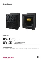
Page 1: ...rid loaded LF loudspeaker pioneerproaudio com For support information such as a installation manual and recommended preset settings for these products visit the website above User s Manual 8 two way Passive Bi amp mid high loudspeaker ...

Page 2: ...en installed in high locations 7 Attachment of the XY 2 as front lower loudspeaker 8 Attachment of the CP XY1VC1 Vertical Flying Cradle 8 Attachment of the CP XY1DF1 as Variable Angle Bracket 9 Assembly of cluster using the CP XY1DF1 Dual Enclosure Flying Plate set 10 Vertical expansion of cluster using the CP XY1CON1 11 Connections XY 1 12 XY 2E 12 Additional information Dimensions XY 1 13 Dimens...

Page 3: ... Keep magnetic objects such as screwdrivers or steel parts away from the tweeter and woofer speakers Since the speakers use strong magnets the objects may be attracted causing injury or damaging the diaphragm Do not install the loudspeaker in areas exposed to direct sunlight or near heating appliances Such conditions may result in shrinkage of the wood materials and finish leading to deformation o...

Page 4: ...s to the wall or ceiling you should first confirm that the wall or ceiling being used is strong enough to support their weight If you are unsure then consult a specialist If the speakers should fall then it could lead to serious injury and is potentially very dangerous Check to make sure that any mounting hardware used is enough to support the system whether using special hardware designed for the...

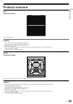
Page 5: ...painting XY 2E Product overview Mid high speaker taken from the mid high range horn section of the XY 3B Features The 8 inch mid range driver and the 1 inch compression driver that delivers clean and precise high and mid range frequencies X Phase system with gold X Phase plug User changeable passive or Bi amp modes Connected to XY 1 vertically to make a Bi amp or Tri amp XY 3 Connected to XY 1 hor...

Page 6: ...amplifier working within its operating range It is good practice to use an amplifier equal to the program power rating of the loudspeaker so as to retain sufficient headroom and good dynamic range Care should be taken during operation to avoid amplifier clipping as this can cause serious damage to your loudspeakers If in doubt please contact your dealer who will be happy to assist you in correct a...

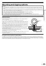
Page 7: ...rom these fixing points by using forged shoulder eyebolts and the optional flying hardware The structure of the M10 threaded fixing points are such that their attached bolts pierce through the speaker enclosure Therefore if these points will not be used the holes must be blocked with the hexagon socket countersunk bolts attached by factory default to ensure that the enclosure is completely sealed ...

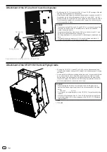
Page 8: ...lts Flat washer and spring washer out of the reach of children and infants If accidentally swallowed contact a doctor immediately Attachment of the CP XY1VC1 Vertical Flying Cradle 1 By using the CP XY1VC1 each XY 1 or XY 2E unit can be suspended and freely adjusted between an angle of 90 degrees from vertically upright to facing downward Ensure that both the flat and locking washers are used the ...

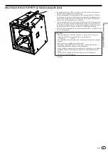
Page 9: ...ot on the last hole and use the point on the rear or underside as a pull back The XY 2 can also be added to the bottom surface of the XY 1 or XY 2E with the CP XY1DF1 attached WARNING When installing the CP XY1DF1 with the XY 1 and XY 2E make sure to tighten the bolts to the torques specified in the table below M10 bolts 15 N m Do not attempt to use this product with components other than the spec...

Page 10: ...rger down tilt angles position the pivot on the last hole and use the point on the rear or underside as a pull back The XY 2 can also be added to the bottom surfaces of the XY 1 and XY 2E linked using the CP XY1DF1 WARNING When installing the CP XY1DF1 with the XY 1 and XY 2E make sure to tighten the bolts to the torques specified in the table below M10 bolts 15 N m When assembling cluster using t...

Page 11: ... four vertical connection plates that come with the metal fittings fix the sides of the top and bottom speakers WARNING When installing the CP XY1CON1 with the XY 1 and XY 2E make sure to tighten the bolts to the torques specified in the table below M10 bolts 15 N m Do not attempt to use this product with components other than the specified speaker Be sure to use the supplied accessory screws Afte...

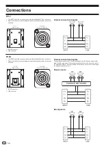
Page 12: ...e mode Initial state to the Bi amp mode When changing the operation mode be sure to refer to the Installation Manual If wiring is carried out incorrectly it may result in damage to the amplifier and speaker unit Passive mode PASSIVE NETWORK Bi amp mode Connections XY 1 The INPUT and LINK connectors used are Neutrik SpeakON NL4 connectors Refer to the internal connection diagram and make the approp...

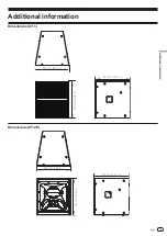
Page 13: ...13 Engb Additional information Dimensions XY 1 530 mm 20 9 in 540 mm 21 3 in 578 mm 22 8 in Dimensions XY 2E 530 mm 20 9 in 540 mm 21 3 in 578 mm 22 8 in Additional information ...

Page 14: ...c internal passive Connectors 2 x Neutrik SpeakON NL 4 Dimensions W H D 530 mm x 578 mm x 540 mm 20 7 inch x 22 8 inch x 21 3 inch Weight 34 0 kg 74 9 lb 29 0 kg 63 9 lb Rigging and Hardware 23 x M10 threaded mounting points 4 top 5 bottom 4 rear 5 left 5 right 2 x Flush handles 1 left 1 right CP XY1VC1 Vertical flying cradle CP XY1DF1 Dual enclosure flying plate CP XY1CON1 Vertical connection pla...

Page 15: ... 0012 JAPAN 220 0012 神奈川県横浜市西区みな とみ らい4丁目4番5号 横浜アイ マークプレイ ス6階 6F Йокогама i Mark Place 4 4 5 Минатомирай Ниси ку Йокогама Канагава 220 0012 ЯПОНИЯ Artemis Building Odyssey Business Park West End Road South Ruislip Middlesex HA4 6QE U K TEL 44 203 7617 220 2050 W 190th Street Suite 109 Torrance CA 90504 U S A TEL 1 424 488 0480 DRB1749 B ...

Reviews: