background image

51

XC-LA21

 115-000920-000A (HNA-09SS20) (DISPLAY CONTROL ASSY : LCD401)

     • FL DISPLAY

7.2.2 DISPLAY

Anode Connection

Pin Connection

Summary of Contents for XC-LA21

Page 1: ... 33 CONTENTS 7 GENERAL INFORMATION 37 7 1 DIAGNOSIS 37 7 1 1 TROUBLE SHOOTING 37 7 1 2 DISASSEMBLY ASSEMBLY 41 7 2 PARTS 49 7 2 1 IC 49 7 2 2 DISPLAY 51 7 3 REMOTE CONTROL UNIT 52 8 PANEL FACILITIES AND SPECIFICATIONS 54 THIS MANUAL IS APPLICABLE TO THE FOLLOWING MODEL S AND TYPE S Component Model Service manual Remarks COMPACT MINI COMPONENT X LA21 RRV2370 STEREO CD TUNER XC LA21 RRV2392 This man...

Page 2: ...ser beam LASER DIODE CHARACTERISTICS MAXIMUM OUTPUT POWER 5 mW WAVELENGTH 760 800 nm IMPORTANT THIS PIONEER APPARATUS CONTAINS LASER OF CLASS 1 SERVICING OPERATION OF THE APPARATUS SHOULD BE DONE BY A SPECIALLY INSTRUCTED PERSON LABEL CHECK 1 SAFETY INFORMATION This service manual is intended for qualified service technicians it is not meant for the casual do it yourselfer Qualified technicians ha...

Page 3: ...3 RCA Audio Cable 122003220100 NSP 4 AAA Size R03 Batteries 130115004000 5 FM Wire Antenna 132030001001 6 Power cord Plug Conversion Adaptor 138011722000 7 Battery Door 500RC4603070 8 Polyform Unit 800PMT190001 9 Polyfoam Speaker 800PMT390000 10 Poly Foam Sheet C SP 801999000002 11 Polythenefoam Sheet 801999000005 NSP 12 PE Polybag AC Cord 805032115000 NSP 13 PE Polybag Remocon 805035105000 NSP 14...

Page 4: ...9 8 16 53 2 8 13 6 15 50 62 15 6 2 8 16 48 35 37 8 47 12 8 58 77 9 8 75 74 46 76 19 16 9 73 80 45 79 81 82 17 60 8 41 10 40 85 52 33 Refer to section 2 3 CD MECHA SECTION 6 6 39 18 26 61 29 8 8 16 36 70 89 69 65 84 44 93 22 55 91 92 94 99 21 67 95 97 24 42 43 23 8 78 90 25 68 98 38 88 63 F A G B E C D 16 96 62 16 96 DDXCN AR Only DDXCN AR Only ...

Page 5: ...eld Plate 650PMT139000 57 58 Display Filter Plate 650PMT147002 59 PC Sheet 650PMT149000 60 Transport Stopper PL 650PMT197010 61 Shielding Plate 650277225000 62 Rubber Foot 700PMT384000 63 Capacitor Boot 700PMT150000 64 Bushing 700PMT156000 65 Cable Plastic Tie 727000100000 66 NSP 67 Trans Stopper Label 809PMT194021 68 AC Cord Label See Contrast table 2 69 Voltage Label See Contrast table 2 70 Warn...

Page 6: ...ECHA SECTION C A C B B A 8 8 3 51 6 41 51 56 50 37 50 2 43 46 55 42 20 53 18 19 49 9 49 8 7 5 8 4 53 52 38 39 40 39 38 27 45 21 24 35 36 48 29 25 26 22 47 11 15 54 23 33 32 57 28 1 53 30 31 44 49 16 48 17 14 12 10 13 34 ...

Page 7: ...3240 23 Arm Stopper A2 45 239 4279 24 Arm Stopper B 45 239 4065 25 Gear Idler A 45 222 4128 26 Gear Idler C 45 222 4051 27 Lever 2 45 259 3289 28 Lifter 45 259 3025 29 Pulley A 45 229 4052 30 Assy Motor CRG S 45 093 4238 31 Assy Motor DRW S 45 093 4239 32 Spring 01 080 4541 33 Spring 01 082 4643 34 Spring 01 082 4647 35 Belt 02 083 4171 36 Belt 02 083 4172 37 Cushion 45 063 4136 38 Insulator 45 06...

Page 8: ... ANTENNA 3 2 1 1 2 CARR FIN RFO RFI CD L 9V CD R CARR DRAW DRAW IC2 TA2065F RF AMP IC1 TC9284BF DECODER IC401 PDA068A SYSTEM CONTROL IC LCD401 FL TUBE IC4 BA4558N IC6 TA7291S DRIVER IC3 TA2092N DRIVER 1 LO 6 RO 2 53 2 7 3 IC7 TA7291S DRIVER 7 3 FE101 T101 T103 1 8 9 1 9 1 27 28 29 30 73 76 VOL JOG KEY INPUT M M 6 1 7 RIN FIN RIN 5V 12 12 24V 14 14 3V8 15 15 P8V 17 17 3V8 9V 8 10 8 10 12 15 12 15 F...

Page 9: ... MCU9V AC3 8V AC3 8V AC3 8V AC24V MCUAC AC3 8V 24V 5V 5V 2 3 4 8 9 10 11 1 2 3 4 8 9 10 11 L R AUXOUT L R AUXIN 5 7 3 1 31 24 L R To M LA21 14 15 13 5 3 2 2 9 3 1 1 2 7 8 9 10 1 2 7 8 9 10 4 11 IC301 9V REG CN302 12P SN302 12P 3 3 9V IC304 6 6 9V 4 2 CN204 3P Q908 Q909 CN208 3P 3 1 AUDIO SIGNAL ROUTE TUNER AUDIO SIGNAL ROUTE RF CD T AUDIO SIGNAL ROUTE AM AM AUDIO SIGNAL ROUTE FM FM AUDIO SIGNAL RO...

Page 10: ...OP CL SW 7 FWD SW 8 1 2 3 4 5 6 7 8 9 10 11 12 13 14 15 16 17 18 19 20 21 22 23 24 25 26 27 28 29 30 1 2 3 4 5 6 7 8 9 10 11 12 13 14 15 16 17 18 19 20 21 22 23 24 25 26 27 28 29 30 CN401 CN205 FWD SW RVS SW OP CL SW CN1 SW CN2 SW HOM SW EXTRA SW DMR DMF CMR CMF CD BUS0 CD BUS1 CD BUS2 CD BUS3 CD CCE CD BUCK CD POWER SYS MUTE CD SW PUIN CLOCK POWER RDS DATA RDS CLOCK NC CHANNEL 0 TUNER CHANNEL 1 V...

Page 11: ...GND R CD AGND AGND AGND 1 2 3 4 5 6 7 8 9 10 11 12 13 14 15 16 1 2 3 4 5 6 7 8 9 10 11 12 13 14 15 16 CN11 CN301 M9V TUNER9V CD9V MCU9V VT POWER CLT CLOCK CLT 5V AC3 8 AC3 8 24V D GND D GND M GND 1 2 3 4 5 6 7 8 9 10 11 12 13 14 1 2 3 4 5 6 7 8 9 10 11 12 13 14 CN302 SN302 AC12V AC12V AC31V AC31VGND AC31V AC24V AC24VGND AC3 8V AC3 8V MCUAC MCUACGND RELAYB 1 2 3 4 5 6 7 8 9 10 11 12 1 2 3 4 5 6 7 8...

Page 12: ...008 685500 000A 037 003534 100 019 000107 006A 012 007840 010A 012 006120 010A 042 104511 000A 118 040102 002A 118 040102 002A 135 006116 160J 135 006232 300J 136 14PMT1 B00J 136 TOCB17 171J 136 FEBTVK 240J 136 03PMT1 B00J 007 200610 000A 009 607200 000A 003 020280 050 003 024010 050 003 020380 050 005 035100 000A 003 050010 050 A 3 3 STD TUNER ASSY ...

Page 13: ...M FM AM AM AM AM FM FM FM FM T T T T T T T T T 010 101837 000A 008 685500 000A 011 010051 120A 018 010014 000A 019 000107 006A 019 000450 012A 012 000120 010A 012 002240 010A 012 7NF803 007A 003 020280 050 003 020280 050 003 020280 050 003 020380 050 003 020380 050 003 020380 050 003 020380 050 003 020380 050 003 020380 050 003 020380 050 003 082110 050 A ...

Page 14: ... 14 A B C D 1 2 3 4 1 2 3 4 CN8 A CD MECHA Decorder 010 849284 000A 008 680500 000A 011 010056 120A 037 003534 100 003 624052 050A 020 001693 000A 003 624052 050A 135 006232 301J 136 08PMT1 250J B 3 4 CD ASSY ...

Page 15: ...AUDIO SIGNAL ROUTE RF CD VREF EFO RFO TSO M M CARRIAGE MOTOR DRAWER MOTOR RF Amp 010 832065 000A 010 832065 000A 008 685500 000A 018 010014 000A 003 624052 050A 002 472065 000A 002 104085 102A 002 104085 102A 002 104085 102A 136 067238 205J 136 04PMT1 250J 135 TOCA16 160A B ...

Page 16: ...J904 118 000244 000A 003 020380 050 008 801144 000A 008 801144 000A 008 801144 000A CN206 A CN11 A CN1 C CN904 D CN13 A AUDIO ASSY PMT101000210 C AUX ASSY PMT1LA100091 D T T AU AU AU AU AU AU AU AU AU AU AU AU AU AU AU AU 9V Reg Selector 004 068350 100 004 068350 100 004 023310 100 004 010310 100 004 010310 100 135 006116 160J 135 PHS030 030J C D E 3 5 AUDIO AUX RECT and TRANS ASSYS ...

Page 17: ...08 685500 000A 011 020005 000A 011 024001 000A 011 024001 000A 011 024001 000A 011 010082 120A 136 09PMT1 C00J 050 120060 251J TRANS ASSY PMT1LA100071 F RECT ASSY PMT1LA100061 E LIVE NEUTRAL NOTE FOR FUSE REPLACEMENT FOR CONTINUED PROTECTION AGAINST RISK OF FIRE REPLACE WITH SAME TYPE AND RATINGS ONLY CAUTION AUDIO SIGNAL ROUTE RF CD TUNER SIGNAL ROUTE T AUDIO SIGNAL ROUTE AUX AU 011 010051 121A 0...

Page 18: ...07 For DOWNLOAD A DISPLAY CTL ASSY PMT101000041 G 110 033045 013A 110 033045 013A 110 033045 013A 110 033040 013A 110 033162 003A 021 114165 000A 006 747300 05CA 001 229103 000A 003 H12203 204A 135 TOCB17 171J 135 FESTVK 240J G 3 6 DISPLAY CTL ASSY ...

Page 19: ... S406 TIMER S407 DISPLAY CLOCK S408 4 1 TUNING S409 TUNING S410 CD SELECT 3 S411 CD SELECT 2 S412 CD SELECT 1 S413 CD3 OPEN CLOSE 0 S414 CD2 OPEN CLOSE 0 S415 CD1 OPEN CLOSE 0 SYSTEM CONTROL IC 003 430050 050 001 220104 000A 001 220104 000A 001 220104 000A 111 000638 000A 115 000920 000A 020 000800 000A 009 332768 100A G ...

Page 20: ...9V CD9V 5 LATCH 4 SP CLT 3 HLCH 1 HRCH 2 D GND 6 DATA 7 CK 8 MUTE 9 CH B 10 CH A 11 CD L 12 A GND 13 CD R 16 LINE MUTE 14 A GND 15 A GND D GND R CH L CH EXTRA SPCLT HOME CN2 CN1 O C FWD RVS DMF DMR CMF CMR CD PWR SLT BUCK CCE B3 B2 B1 B0 M GND A GND D GND M 9V CD 9V CD L CD R 10 6V 13 GND 3 TUNER 2 CH 0 4 CH 1 6 VOL LATCH 8 POWER CTL 15 P8V 5 VOL DATA 7 VOL CLOCK 9 DTS CLOCK 11 DTS PERIOD 16 DTS D...

Page 21: ...R129 R167 R168 R165 R166 R130 R173 R133 C132 R128 C128 R163 R164 C196 C133 C170 C169 R132 C197 C135 C129 C147 CF103 7 W143 Q105 W135 R146 5 R150 C139 R177 C158 L102 C148 C151 C150 R144 C152 C154 R149 CX101 IC102 R104 R110 C106 C121 R151 C156 R152 Q117 Q116 C105 R109 C111 R108 R106 R107 C109 Q102 R105 C108 CF101 R102 R101 C107 C104 R103 Q101 C103 C102 C101 FE101 R115 C119 T101 Q107 VD103 C120 TC101...

Page 22: ...DGND R CH PMT 1 01 03 1 1 16 E E E E E E E E C54 C75 W49 C56 W38 4 1 2 3 CN6 W36 W6 R72 R73 W37 CN3 VR3 W23 R39 R95 R94 W25 R36 D1 W42 CN1 W32 W33 W3 W26 W19 C4 C35 W8 C36 C22 W39 W45 W44 W46 W48 W47 R61 R60 R35 R56 R57 R58 R59 W43 W41 W40 W34 W30 W1 W2 W4 W5 W7 W21 C39 W14 W10 W9 W12 W11 R34 W22 W28 W27 W24 R67 R28 R33 R68 C49 C50 R40 W35 R41 C41 R92 W15 W17 W16 W13 R2 R1 W18 W20 CN5 CN2 C73 C72 ...

Page 23: ...D M D M 5 1 10 5 1 15 20 5 1 30 25 20 15 10 5 5 1 EXTRA HOME COM CN2 CN1 OP CL FWD RVS 5 5 1 1 1 CARR CARR DRAW DRAW 80 75 70 65 60 55 50 45 40 35 30 25 20 15 10 5 38 24 15 1 48 45 40 35 30 25 20 14 10 5 1 PMT 1 01 03 R96 R32 R75 R77 R74 R76 R83 C26 C28 R30 R24 R31 R29 R27 R26 R25 C8 C43 C15 C1 R15 R82 C17 C32 R17 C24 C44 R23 R22 R16 R6 C25 C2 C14 R5 C 2 9 C46 W 3 1 R37 C59 R54 C60 C57 C53 C52 R 5...

Page 24: ...262 C270 C215 W269 W267 R291 R292 R294 R293 Q258 Q259 Q261 Q260 Q257 D252 C260 C225 R283 R217 Q201 C212 IC202 R216 C214 C216 C220 C221 C226 Q251 R219 C228 C224 C223 C206 C210 C222 R226 R225 R227 C204 R211 C213 C227 C211 CN202 C203 C233 IC201 R214 16 AGND AGND AGND DGND HPGND DGND GND 9V 31V GNDB GND AUDIO BOARD 1 15 10 5 1 1 15 10 5 1 1 5 1 AC VIDEO MUTE AGND AGND AGND TUN L TUN R AGND AGND 31V PG...

Page 25: ... R269 C271 C264 R266 R270 C259 R263 C260 R264 C266 R276 R274 R275 C267 C269 R278 IC251 D251 R273 C265 R268 R260 C252 R253 R252 C257 R258 C256 R256 C255 R257 R281 C254 R283 R286 R289 R288 C272 D255 R265 Q252 RL251 C258 R279 R287 Q251 Q253 R262 R261 C251 R255 C253 R259 R272 Q256 D253 Q255 12 6 18 1 AGND AGND AGND 31V GNDB GND 31V 31V 10 5 1 5 1 1 15 10 5 1 C VIDEO MUTE A3 D D V D D V RCTRL AGND AGND...

Page 26: ...AC 12V AC 31V AC 31V GND AC 31V AC 24V AC 24V GND AC 3 8V AC 3 8V MCU AC MCU AC GND RELAY B AC 12V AC 12V AC 31V AC 31V GND AC 31V AC 24V AC 24V GND AC 3 8V AC 3 8V MCU AC MCU AC GND RELAY B IC303 IC304 IC305 IC307 GRY WHT PUR BLU GRN YEL ORN RED BRN RED PRIMAR DANGER PMT1LA RECTIFIER BOARD TRANSF 1 1 5 5 10 10 12 12 14 10 5 1 5 1 5V MCU8V M8V A GND TUNER8V CD8V POWER GND 31V 31V S GND D GND 8V AC...

Page 27: ... LA21 27 A B C D 5 6 7 8 5 6 7 8 F PT1 ORN YEL N L TF303 RL301 R308 C316 C315 L301 W307 W306 D311 SW301 SW302 F306 PRIMARY DANGER PMT1LA 01 07 TRANSFORMER BOARD N L TRANS ASSY F AC IN LIVE NEUTRAL SIDE A ...

Page 28: ...W915 W914 W913 C921 C922 C923 C931 C930 R959 R958 CN202 CN201 R955 Q912 R954 R953 C924 C925 W910 R952 R951 R950 R949 C920 R937 R901 R902 C901 J201 R945 Q910 Q909 Q908 R944 C926 R942 R943 R940 R939 R941 Q901 R912 Q902 R911 Q903 W902 GND W912 W903 W906 J902 J903 J904 W904 W905 R904 R914 R935 C928 C905 C929 C909 C902 R907 R917 R908 R909 C907 C903 C910 R915 R905 R916 R906 C908 R910 IC901 R903 R913 C90...

Page 29: ...406 LED403 LED402 LED401 SW405 SW406 SW407 S409 S408 S401 S414 S415 S412 S411 S402 S413 S410 S403 S404 I C 4 0 1 PMT1 01 05 5V 5V DGND DGND 24V 5V 24V DGND AC3V8 P9V AC3V8 5V 5V 5V CONTROL BOARD DISPLAY BOARD 1 1 10 5 1 5 10 15 20 10 5 5 1 15 10 DIS CLT GND KEY 2 KEY 1 KEY 0 9V D3 LED D2 LED D1 LED 5V DIS CLT GND KEY 2 KEY 1 KEY 0 9V D3 LED D2 LED D1 LED 5V CLOCK TIMER ENTER PLAY PAUSE STOP UP DOW...

Page 30: ...T PF120C 10mm 012 000120 010A T105 IFT 4A 224R 10mm 012 002240 010A T103 IFT 1A612R 10mm 012 006120 010A T101 IFT 1A784R MW RF 10mm 012 007840 010A T106 IFT FM DET 600TEAS 012 7NF803 007A FE101 TUNER FN 00STATION 042 104511 000A P101 JP WIRE AWG26 110mm 051 675110 009J SHIELD WIRE SINGLE 053 103077 015J CN101 CN102 EXT SP JACK 118 040102 002A CN206 FFC CONN SOCKET 16P 135 006116 160J CN8 FFC CONN ...

Page 31: ...J CN5 HSG PMT1 4A JST 136 04PMT1 250J CN4 HSG 2CD9 6C REV 136 067238 205J CN2 HSG PMT1 8A JST 136 08PMT1 250J SOLDERING PIN 137 300000 002J X1 CERAMIC RESONATOR 020 001693 000A 16 93MHz AUDIO ASSY SEMICONDUCTORS IC201 BU4052BC IC202 BH3854FS Q201 2SC1815 D201 MTZJ4 7B D202 D203 1N4148 D204 D206 ZENER 05AZ4 7 011 010051 121A D209 MTZJ9 1B D255 RECTIFIER IN 4001B 011 024001 000A CAPACITORS C203 CEAT...

Page 32: ...041 000A SLIDE SW VOLT SELECTOR 117 220V RL301 RELAY 9V SDT S 109LMR 128 090109 000A CAPACITORS C315 C316 003 010320 250A CERAMIC CAP 0 01 uF 250V OTHERS JP WIRE AWG22 UL1672 051 265160 003J JP WIRE AWG22 YELLOW 051 265180 010J AC CONTACT TERMINAL 137 400001 000J F306 FUSE HOLDER 7900 550 790000 000J DISPLAY CTL ASSY SEMICONDUCTORS IC401 PDA068A Q402 Q405 DTC114ES Q406 2SC1815 D402 D403 D401 D404 ...

Page 33: ... Instruments 2 Necessary Adjustment Points 6 1 CD SECTION 6 1 1 PREPARATIONS CD ASSY is taken out according to the procedure of DISASSEMBLY And please adjust the part CD after connecting connectors When Exchange PICKUP 1 2 3 4 1 2 3 4 1 2 3 4 Exchange CD ASSY Exchange SERVO MECH ASSY Adjustment Points Pages 35 and 36 Pages 35 and 36 Pages 35 and 36 6 ADJUSTMENT ...

Page 34: ... C48 C38 C16 C20 C27 C65 C68 VR2 VR1 VR4 L1 CN4 C31 C29 C12 C9 IC3 TEO TEB FEO FEO C CD 5V GNDCD GNDCD GNDCD GNDCD GNDM CD 9V GNDM GNDCD CD 5V RED O BOARD 5 1 20 15 10 5 1 RFO FEO TSO VREF 1 GND SLT FM FM DM DM VR1 FOCUS BALANCE VR2 TRACKING BALANCE VR4 FOCUS OFFSET VR3 TRACKING OFFSET Fig 1 Adjustment Locations CD ASSY 6 1 2 Adjustment 1 Adjustment Locations SIDE A RFO VREF FEO TSO ...

Page 35: ...ocus Offset DC voltage 0 10 mV Oscilloscope DC Mode V 50mV div H 1mSec div GND Probe Player START CD ASSY FEO VREF 4 1 2 Tracking Offset TEO Adjustment FUNCTION CD CD in stop mode VR3 Tracking Offset DC voltage 0 10 mV Oscilloscope DC Mode V 50mV div H 1mSec div GND Probe Player START CD ASSY TSO VREF ...

Page 36: ...s made a center A B symmetry ADJ Oscilloscope DC Mode V 100mV div H 1mSec div GND Probe Player A B NG OK NG A B CD ASSY TSO VREF START 4 1 4 Focus Balance FEB eye pattern RF level Adjustment FUNCTION CD TEST DISC PLAY VR1 Focus Balance maximum Obtain maximum 3T level of EYE pattern 1 2Vp p 3T Oscilloscope AC Mode V 200mV div H 0 5µSec div GND Probe Player START CD ASSY RFO VREF ...

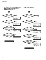
Page 37: ...pply YES Are CLOCK CLT pin 6 of CN301 and pin 80 of IC401 high level Are the XT1 and XT2 pin 12 and 13 of IC401 oscillated in 32 768kHz YES Are the CF1 and CF2 pin 15 and 16 of IC401 oscillated in 8MHz YES Is the RES pin pin 11 of IC401 has a low pulse input while the power cord plug in Or the RES pin return to high finally NO NO NO NO NO Please check the corres ponding control circuit transistor ...

Page 38: ...5 or IC6 broken NO 3 Can you hear the sound of CD Changer Mechanism or clamper movement when power cord plug in YES Have noise come out YES Do pin 12 VDD of IC102 have 5V Do pin 6 TUN of IC102 have a 0V YES YES Is the waveform of pin 3 4 and 5 of IC102 correctly when the tuner is in scan the frequency NO Please check the pin 1 of CN11 in 8V and the corres ponding power circuit on the Tuner board D...

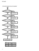
Page 39: ...ecting the corresponding CD1 2 3 EJECT key to close the CD tray Please press CD PLAY PAUSE key or CD SELECT key of DISC No Please tune the CD again NO Please check the CD sleding circuit and tune the CD again Please check 3P 4P of CN4 and 9P 11P of IC3 Please check the connection CN3 and 5P 2P 4P of IC3 Please check the connection CN3 and 5P 2P 4P of IC3 Please check the connection CN4 and 8P 9P 1...

Page 40: ...se check IC301 and its corresponding circuit Check the pins 9 B and 10 A of the IC201 Is the value is corrected according to Table 1 Is the pins 18 19 and 20 of the IC202 had correct waveform when the volume is adjusting YES YES Do the corresponding Audio input signal on IC201 correctly Do the audio output from the pins 3 and 13 of IC201correctly E 6 No audio signal come out on speaker NO NO YES N...

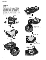
Page 41: ...ear side Side Panel L Remove as well as Side Panel R 4 STANDBY ON or CD OPEN CLOSE Unook Tray Panel Set Drawer Flat Blade Screwdriver 9 11 10 11 11 12 Unhook 5 Unhook Top Panel 5 13 8 7 1 2 DISASSEMBLY ASSEMBLY 1 Main Body Section 2 14 15 15 15 Remove as well as Side R 15 16 16 17 Draw out the CD MECHA by pushing the hook CD MECHA 2 6 1 ...

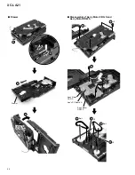
Page 42: ...etc occurring and remove Tray Panel Set Slider 2 of the CD MECHA is moved from the ditch of the chassis on the bottom side of the product with a minus driver and Drawer is drawn out Afterwards please remove Front Unit after removing Tray Panel Set 1 2 2 3 4 3 1 CD MECHA Carriage 300 Ass y Clamper S0 Bottom Side Bottom Side 2 2 2 2 5 6 6 Bottom Side 7 8 11 12 12 9 8 Lift up Disconnect the Hook Pick...

Page 43: ...e Assy Gear Drive which connects Assy Holder L with R The position match of each gear is necessary 3 Please do not lose the gear Bevel Gear 4 and Gear Idler A not fixed while put in the axis Carriage 100 Method of distinguishing the back of Carriage Method of distinguishing surface of Carriage Carriage 200 Carriage 300 Carriage 100 1 Carriage 200 2 Carriage 300 3 4 Carriage 300 is put in the Chass...

Page 44: ...LA21 7 Drawer 1 2 4 2 Bottom Side Disconnect the Hook 3 7 Disassembly of Ass y Motor CRG S and Ass y Motor DRW S 1 Ass y PC Board A Belt Drawer Ass y Motor CRG S Ass y Motor DRW S 2 2 1 2 2 3 Belt 3 4 2 4 2 3 ...

Page 45: ...er 2 7 8 9 Spring 10 11 Belt Arm Stopper B Ass y Slider 2 Hook 7 Chassis Disconnect the Hook Lifter Spring Lifter Spring 5 6 Carriage 300 Ass y Clamper S0 1 4 3 2 Lift up Bottom Side 1 The loss of this gear is noted ...

Page 46: ...ction of black Cam Carriage 100 is No 1 carriage Carriage 200 is No 2 carriage After Bevel Gear is turned counterclockwise and five rotations are made after lower side Pinion begins to turn stops in the place where its rotation stopped 4 Carriage 200 3 The bottom of Carriage is hit under right Stopper and puts Carriage 200 2 The first teeth of Carriage are put between the pin and the pin lower sid...

Page 47: ...kwise direction of a rear side from a front side until Carriage 100 bumps to the wall on a front side 11 The position of a right and left black cam is matched while confirming it from the table side of Drawer Cam Mark Cam Mark Meanwhile Mark of right and left black Cam is matched Bevel Gear is turned clockwise direction of a rear side from a front side 3 3 Hang Carriage only here of Pinion FRONT s...

Page 48: ... in neatly in order of Carriage 200 and 100 3 Arm Stopper B is moved horizontally inside as shown in the figure below 4 Pulls Slider 2 until the lock comes off to the direction of ta front side 7 Assembly of Drawer and Chassis A A B B Coming off of a black gear is noted Coming off in the spring is noted The lock comes off Slider 2 Direction of front Arm Stopper B Note Do not lift Arm Stopper B for...

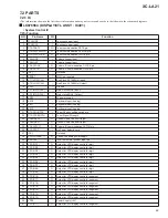
Page 49: ...i d u A l o r t n o C 5 2 H C T A L L O V O n i p H C T A L n o i t a c i n u m m o c C I e m u l o V 6 2 P O T S S Y S I n i p n o i t c e t e d r e w o P o N 7 2 C N d e s u t o N 8 2 R E W O P S Y S O y l p p u s r e w o p o i d u a e h t l o r t n o C 9 2 E T O M E R I n i p t u p n i r e v i e c e r e t o m e r d e r a r f n I 0 3 1 D G D F V O t i g i d r e l l o r t n o c y a l p s i d D F ...

Page 50: ...h C 0 7 W S E M O H I h c t i w s n o i t i s o P e m o H e g a i r r a C r e g n a h C 1 7 W S A R T X E I h c t i w s n o i t i s o P a r t x E e g a i r r a C r e g n a h C 2 7 4 D D V V 5 y l p p u S r e w o P 3 7 R M D O l o r t n o c e s r e v e R r o t o M r e w a r D 4 7 F M D O l o r t n o c d r a w r o F r o t o M r e w a r D 5 7 R M C O l o r t n o c e s r e v e R r o t o M e g a i r r ...

Page 51: ...51 XC LA21 115 000920 000A HNA 09SS20 DISPLAY CONTROL ASSY LCD401 FL DISPLAY 7 2 2 DISPLAY Anode Connection Pin Connection ...

Page 52: ...XC LA21 52 A B C D 1 2 3 4 1 2 3 4 7 3 REMOTE CONTROL UNIT 7 3 1 SCHEMATIC DIAGRAM ...

Page 53: ...r Slow Slow Angle Subtiitle Setup Return On Off Subtitle 0 Clear Audio Prog A B Repeat Disply 9 8 7 6 5 4 3 2 1 V Enter V Mute Zoom Menu Title Open Close Power IC801 24 13 12 1 IC801 Vol Tre Bass Enter Vol Time Digest Slow Step Sarch Repeat Return PBC Random Pgm C 0 10 0 7 8 9 CD 3 CD 2 6 5 4 CD 1 3 2 1 Mode Play F B F F Stop Play Pause Mono Tuner Aux CD Snooze Sleep Timer Dimmer Clock Display Pow...

Page 54: ...54 XC LA21 8 1 PANEL FACILITIES 8 PANEL FACILITIES AND SPECIFICATIONS Front Panel LA21 3 COMPACT DISC MULTI CHANGER STEREO CD TUNER 1 2 3 4 5 6 8 9 7 10 11 12 13 ...

Page 55: ... tone of the sound 4 Fluorescent display 5 FUNCTION Turn to select the source to listen to CD radio or an external component 6 Disc tray 7 Disc indicators Indicate whether a disc is loaded in that disc tray blinks while loading lights when loaded 8 OPEN CLOSE 0 Use to open or close indi vidual disc trays Also switches the system on if it was in standby 9 1 4 TUNING When using the CD player use to ...

Page 56: ...r fast reverse forward play When listening to the radio use for turning and use to tune into stations and select preset stations 13 ENTER Use to save a radio station preset set the clock or timer 14 7 Press to stop playback Also cancels auto scan tuning 15 Number buttons When playing CDs use to select track numbers When listening to the radio use to select preset stations 16 C Press to clear a CD ...

Page 57: ...e Total including M LA21 538 W Power Consumption Standby mode 1 W Dimensions Stereo CD tuner 160 W x 176 H x 323 5 D mm Stereo power amplifier 160 W x 176 H x 315 D mm Weight Stereo CD tuner 4 0 kg Stereo power amplifier 5 1 kg Accessories Operating instructions 1 Remote control unit 1 FM wire antenna 1 AM loop antenna 1 AAA size R03 batteries 2 RCA audio cable 1 Power cord plug conversion adaptor...

Reviews: