background image

XC-L11

10

A

B

C

D

1

2

3

4

1

2

3

4

IC3502

(BA4558F)

IC3503

(BA4558F)

IC3501

(BU4052BCF)

BALANCED 

)

BALANCED 

AMP

FUNCTION

SW

VOLTAGE SUPPLY 

for FL

BALANCED 

BUFFER(-)

7

5

7

5

IC3504

(BA4558F)

3

1

IC5701

(BU1923F)

IC5501

(PDC079A)

RDS

µ

-COM

13

15

14

11

12

Q3503

CD MUTE

IC502

V-9

V+9

V+9

V-9

V-5

FLAC

V-40

V+5

V+10

IC501

Q501

V+12

VE+5BU

VE+5

Q5501

D5503

IC551

Q551, Q552

D551-D556

4

2

6

FM/AM TUNER MODULE
(AXQ7229)

A

B

1/3 - 

B

3/3

MOTHER ASS'Y  
 (AWU7836)

B

LOADING MECHANISM
ASS'Y (AXA7101)

IC1101

(TA2150FN)

IC1201

(TC9495F)

IC1301

(M56788FP)

RF AMP.

SERVO

DSP

D/A

DRIVER

25

85

9

38

DOUT

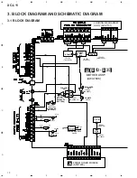
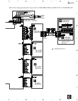
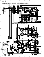
3. BLOCK DIAGRAM AND SCHEMATIC DIAGRAM

3.1 BLOCK DIAGRAM

Summary of Contents for XC-L11

Page 1: ...TIONS 44 T ZZR JUNE 2001 Printed in Japan STEREO CD TUNER PLAY PAUSE STANDBY ON 6 OPEN CLOSE STOP 0 7 Type Model Power Requirement XC L11 ZVYXJ DC power supplied from other system component THIS MANUAL IS APPLICABLE TO THE FOLLOWING MODEL S AND TYPE S Remarks This products are component of systems This product does not operate normally by itself Please connect it to the STEREO CD TUNER XC L11 and ...

Page 2: ...Caution WARNING Lithium batteries Danger of explo sion Replacement must be done by qualified personnel and only by fol lowing the instructions given in the service manual This warning is stated on the product or in the operating instructions When replacing the lithium batteries follow the note below Dispose of the used battery promptly Keep away from children Do not disassemble and do not dispose ...

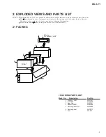
Page 3: ...ance of the safety factor of the part Therefore when replacing be sure to use parts of identical designation Screws adjacent to mark on the product are used for disassembly PACKING PARTS LIST Mark No Description Part No 1 DISPLAY UNIT AXX7107 2 Front Pad AHA7340 3 Rear Pad AHA7341 4 Spacer NS2001 AHB7056 5 Packing Case CD Y AHD7988 6 Packing Sheet AHG7073 7 Seat Z23 007 6 1 3 4 5 7 2 Refer to 2 4 ...

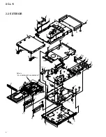
Page 4: ...B B C A H 1 4 3 5 11 37 15 14 24 44 43 43 44 44 42 44 45 44 44 44 44 44 42 42 42 42 25 8 9 44 16 18 34 31 31 35 30 33 28 29 20 30 36 32 12 6 2 D E B G F A Refer to 2 3 LOADING MECHANISM ASSY 21 27 17 38 21 39 40 41 46 20 2 2 EXTERIOR ...

Page 5: ...te ANF7027 NSP 18 Top Plate ANF7028 19 20 Sensor Plate ANG7360 21 Leg AEB7090 22 23 24 Lead Barrier AEC7361 25 Wire Barrier AEC7379 26 NSP 27 PC Support VEC1749 28 Sensor Button L AAD7622 29 Sensor Button R AAD7623 30 Illuminate Lens AAK7896 31 Side Line AAP7088 32 Bottom Base AMA7025 33 Top Panel 1 AMB7779 34 Top Panel 2 AMB7755 35 Button L Assy AXG7110 36 Button R Assy AXG7111 37 Tray Cap Assy A...

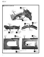
Page 6: ...LOADING MECHANISM ASSY A A 2 8 3 5 4 8 8 12 13 17 21 16 22 15 14 22 22 22 20 18 19 9 1 7 11 27 6 8 25 25 24 C Lubricating Oil GYA1001 Refer to Application of Lubricant Note Lubricating Oil GYA1001 23 Daifree GEM1036 ...

Page 7: ...EB1330 10 11 Loading Base VNL1917 12 Float Base CD ANW7233 13 Drive Cam VNL1919 14 Gear Pulley VNL1921 15 Loading Gear VNL1922 16 Drive Gear VNL1923 17 SW Lever VNL1925 18 Clamper Plate CD ANB7261 19 Bridge VNE2252 20 Clamper CD ANW7234 21 Screw JGZ17P028FMC 22 Screw Z39 019 23 Tray VNL1920 24 Screw PBA1069 25 Screw ABA7069 26 27 Clamp Magnet AMG7006 Mark No Description Part No LOADING MECHANISM A...

Page 8: ...rive Cam No 13 Drive Cam No 23 Tray No 23 Tray Top View Rear View Top View Bottom View Daifree GEM1036 Daifree GEM1036 Daifree GEM1036 Daifree GEM1036 Daifree GEM1036 Side of the rib Inner side of a ditch Inner side of a ditch Lubricating Oil GYA1001 Lubricating Oil GYA1001 Inner side of a ditch Lubricating Oil GYA1001 Lubricating Oil GYA1001 Lubricating Oil GYA1001 ...

Page 9: ...AWU7854 2 CNB ASSY AWU7855 3 Leg AEB7090 4 Window AAK7889 5 Deco Screw ABA7072 6 FL Filter AEC7195 7 Display Panel AMB7750 8 Display Cover AMC7048 9 Screw BPZ30P080FZK 10 Screw PSC30P080FNI 11 DISPLAY UNIT AXX7107 DISPLAY UNIT PARTS LIST H 1 7 4 8 6 9 10 11 I 2 5 3 3 ...

Page 10: ...1 PDC079A RDS µ COM 13 15 14 11 12 Q3503 CD MUTE IC502 V 9 V 9 V 9 V 9 V 5 FLAC V 40 V 5 V 10 IC501 Q501 V 12 VE 5BU VE 5 Q5501 D5503 IC551 Q551 Q552 D551 D556 4 2 6 FM AM TUNER MODULE AXQ7229 A B 1 3 B 3 3 MOTHER ASS Y AWU7836 B LOADING MECHANISM ASS Y AXA7101 IC1101 TA2150FN IC1201 TC9495F IC1301 M56788FP RF AMP SERVO DSP D A DRIVER 25 85 9 38 DOUT 3 BLOCK DIAGRAM AND SCHEMATIC DIAGRAM 3 1 BLOCK...
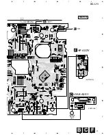
Page 11: ...T AXX7107 HP ASS Y AWU7840 F KEYL ASS Y AWU7839 E KEYR ASS Y AWU7838 D CNB ASS Y AWU7855 I FLDP ASS Y AWU7854 H FLAC ASS Y AWU7837 G C LOADING MOTOR ASSY VXX2505 LOAB ASSY VWG2279 AUDIO SIGNAL ROUTE C Note When ordering service parts be sure to refer to EXPLODED VIEWS and PARTS LIST or PCB PARTS LIST ...

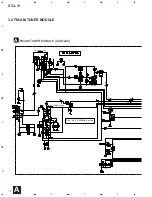
Page 12: ...XC L11 12 A B C D 1 2 3 4 1 2 3 4 FM FRONT END MW RF TUNING BLOCK FM AM TUNER MODULE AXQ7229 A OSC 981 2052kHz 9k step AM AM AM AM AM AM FM FM FM FM FM FM FM FM FM FM A 3 2 FM AM TUNER MODULE ...

Page 13: ...B C D 5 6 7 8 5 6 7 8 2 3 B CN 1 L201 ATE7003 AUDIO SIGNAL ROUTE TUNER TX AM SIGNAL ROUTE AM FM SIGNAL ROUTE FM AM AM FM AM AM AM AM AM AM FM AM FM TX TX TX TX TX FM The power supply is shown with the marked box A ...

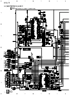
Page 14: ... 14 A B C D 1 2 3 4 1 2 3 4 1 2 VC To CD PICK UP To CD MECHA CN601 C T T F F L L S S C C F T T T F T T L C L S S C F T C L T S S F F T F C DRIVER RF AMP B 1 3 MOTHER 1 3 ASSY AWU7836 1 3 B 3 3 MOTHER 1 3 ASSY ...

Page 15: ...v VC IC1101 Pin19 VC 2 0Vp p Note The encircled numbers denote measuring point in the schematic diagram VC FOCUS SERVO LOOP LINE F TRACKING SERVO LOOP LINE T SPINDLE SERVO LOOP LINE S CARRIAGE SERVO LOOP LINE C LOADING SERVO LOOP LINE L CD AUDIO SIGNAL ROUTE The power supply is shown with the marked box B 2 3 B2 3 F T T F S C DECODER 1 3 B ...

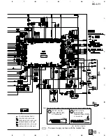
Page 16: ...XC L11 16 A B C D 1 2 3 4 1 2 3 4 B 3 3 B 3 3 B3 3 B1 3 From M L11 T0 CT L11 MJ L11 TX A A A A A REC REC PB PB PB 2 3 B 3 4 MOTHER 2 3 ASSY ...

Page 17: ... 8 5 6 7 8 B 2 3 MOTHER 2 3 ASSY AWU7836 CN201 A The power supply is shown with the marked box TUNER AUDIO SIGNAL ROUTE TX AUX AUDIO SIGNAL ROUTE A REC AUDIO SIGNAL ROUTE REC PB AUDIO SIGNAL ROUTE PB AUDIO SIGNAL ROUTE 2 3 B ...

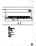
Page 18: ...XC L11 18 A B C D 1 2 3 4 1 2 3 4 FLAC ASS Y AWU7837 G B 2 3 B 2 3 B 3 3 MOTHER 3 3 ASSY AWU7836 Binder G 3 3 B 3 5 MOTHER 3 3 FLAC KEY R KEY L and HP ASSYS ...

Page 19: ...r supply is shown with the marked box KEY L ASS Y AWU7839 E KEY R ASS Y AWU7838 D HP ASS Y AWU7840 F KEY R ASSY S5904 7 STOP SENS 1 Touch Sensor Open Close KEY L ASSY S5903 Stand by ON SENS 2 Touch Sensor Play Pause 8 Shield Case D E F G 3 3 B ...

Page 20: ...XC L11 20 A B C D 1 2 3 4 1 2 3 4 H I 5 1 FLDP ASSY AWU7854 H CNB ASSY AWU7855 I 3 6 FLDP and CNB ASSYS ...

Page 21: ...XC L11 21 A B C D 5 6 7 8 5 6 7 8 H ...

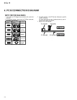
Page 22: ...ts for several destinations For further information for respective destinations be sure to check with the schematic diagram 4 View point of PCB diagrams Symbol In PCB Diagrams Symbol In Schematic Diagrams Part Name B C E D D G G S S B C E B C E D G S B C E B C E B C E Transistor Transistor with resistor Field effect transistor Resistor array 3 terminal regulator Capacitor Connector P C Board Chip ...

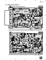
Page 23: ...XC L11 23 A B C D 1 2 3 4 1 2 3 4 ANP7338 B ANP7338 B CN1 B FM AM TUNER MODULE A FM AM TUNER MODULE A SIDE A SIDE B IC201 Q205 Q204 Q203 IC202 Q201 Q202 4 1 FM AM TUNER MODULE A ...

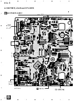
Page 24: ...XC L11 24 A B C D 1 2 3 4 1 2 3 4 OPT OUT IC5701 IC3506 IC5501 IC501 IC502 IC3501 ANP7409 B MOTHER ASSY B From M L11 From MJ L11 or CT L11 CD MECHA CN115 G TUNER MODULE A B 4 2 MOTHER LOAB and HP ASSYS ...

Page 25: ...XC L11 25 A B C D 5 6 7 8 5 6 7 8 B C SIDE A IC1101 IC1301 ANP7409 B HP ASSY F IC3002 IC1201 CN111 To CD MECHA E 110 D LOADING MOTOR ASSY M VNP1836 B LOAB ASSY C F ...

Page 26: ...XC L11 26 A B C D 1 2 3 4 1 2 3 4 B VNP1836 B LOAB ASSY C Q3004 Q3003 Q5952 Q5905 Q5901 Q1102 IC1201 IC1301 Q1101 IC1101 ANP7409 B ANP7409 B MOTHER ASSY B HP ASSY F Q1201 IC3002 Q1301 Q5506 Q3001 C F ...

Page 27: ...XC L11 27 A B C D 5 6 7 8 5 6 7 8 B SIDE B Q1301 Q3505 Q3501 Q3502 Q3572 IC3504 Q3505 Q3503 Q3571 IC5501 Q5505 Q5501 Q5503 Q5506 ...

Page 28: ...28 A B C D 1 2 3 4 1 2 3 4 D E 4 3 KEYR KEYL and FLAC ASSYS ANP7409 B ANP7409 B IC5601 Q5605 Q5606 Q5904 Q5903 Q5603 Q5604 IC5601 KEYR ASSY D KEYL ASSY E FLAC ASSY G 10 B CN11 B CN15 B CN5651 I SIDE A SIDE B G ...

Page 29: ...XC L11 29 A B C D 1 2 3 4 1 2 3 4 ANP7412 B SIDE B ANP7412 B ANP7412 B FLDP ASSY H CNB ASSY I CN2 G SIDE A ANP7412 B Q5661 Q5681 IC5661 4 4 FLDP and CNB ASSYS I H ...

Page 30: ... in the following examples Ex 1 When there are 2 effective digits any digit apart from 0 such as 560 ohm and 47k ohm tolerance is shown by J 5 and K 10 560 Ω 56 101 561 RD1 4PU 5 6 1 J 47k Ω 47 103 473 RD1 4PU 4 7 3 J 0 5 Ω R50 RN2H R 5 0 K 1 Ω 1R0 RS1P 1 R 0 K Ex 2 When there are 3 effective digits such as in high precision metal film resistors 5 62k Ω 562 101 5621 RN1 4PC 5 6 2 1 F Mark No Descr...

Page 31: ... C3521 C3522 CEAT2R2M50 C508 CEAT470M16 C5501 CEJQ100M50 C3009 CEJQ221M6R3 C3537 C3538 CKSQYB104K25 C1241 C1249 C1250 C5507 C5508 CKSRYB102K50 C5801 C5802 C5953 C5954 CKSRYB102K50 C1103 C1107 C1114 C1130 C1204 CKSRYB103K50 C1206 C1207 C1212 C1214 C1223 CKSRYB103K50 C1225 C1227 C1232 C1239 C1245 CKSRYB103K50 C1315 C1316 C1330 C1652 C1653 CKSRYB103K50 C3008 C3010 C3013 C3509 C3510 CKSRYB103K50 C3550...

Page 32: ...15S SWITCHES AND RELAYS S5903 ASG7013 CAPACITORS C5902 CKSRYF104Z25 RESISTORS Other Resistors RS1 16S J OTHERS CN111 9P FFC CONNECTOR 52045 0945 HP ASSY SEMICONDUCTORS Q3003 Q3004 2SD2114K Q3001 DTA124EUA CAPACITORS C3903 C3904 CKSRYB103K50 C3901 C3902 CKSRYB473K25 RESISTORS Other Resistors RS1 16S J OTHERS 112 6P CABLE HOLDER 51048 0600 3901 MINI JACK AKN7026 J 12 6P JUMPER WIRE D20PYY0605E KN390...

Page 33: ...33 XC L11 Mark No Description Part No Mark No Description Part No LOAB ASSY SWITCHES AND RELAYS S101 VSK1011 OTHERS CN602 CONNECTOR POST S2B PH K CN601 CONNECTOR POST S5B PH K PC BOARD LOAB VNP1836 J ...

Page 34: ...o operate only in the CD tuner even if the part AMP is not connected An initial function becomes CD if the product starts in this mode and CD becomes CD TEST mode different from a usual operation Even if the function is returned to the CD function again the product does not become CD TEST mode when the function is made functions other than CD once The product becomes a usual CD operation To put th...

Page 35: ...N The tracking servo is turned off and MUTE is put SERVO OFF VOL UP TRK UP A210 When TRK SERVO ON The tracking servo is turned off MUTE is put and the slider is moved in the direction of FWD CD XX XX SERVO OFF VOL DOWN TRK DOWN A211 When TRK SERVO ON The tracking servo is turned off MUTE is put and the slider is moved in the direction of RVS CD XX XX SERVO OFF None 3 PGM A20D When CD has Stopped L...

Page 36: ...Adjust point Contents Frequency MHz Modulation 1 T METER Adjustment 98 OFF 80 L201 Adjust L201 so that the DC voltage between Pin 21 and Pin 23 of IC201 Test point Vtm gets within 0 50mV AM Tuner Section There is no adjustment in the AM tuner FM75Ω antenna terminal Fig 1 Adjustment Wiring Diagram Fig 2 Adjustment Point FM Tuner Section Set the mode selector to FM BAND Connect the wiring as shown i...

Page 37: ...d Top Plate 1 1 2 1 1 2 2 1 1 1 1 1 4 2 1 3 2 1 3 3 Bonnet Top Panel 1 Top Panel 2 Illuminate Lens Illuminate Lens Illuminate Lens Top Plate Illuminate Lens hook hook KEYR Assy KEYL Assy 7 1 DISASSEMBLY DIAGNOSIS OF PCBs 1 7 GENERAL INFORMATION ...

Page 38: ...38 XC L11 CD MECHA CD MECHA 2 2 2 2 The binder is removed 1 PCB Location KEYL ASSY E LOAB ASSY C HP ASSY F KEYR ASSY D FLAC ASSY G FM AM TUNER MODULE A MOTHER ASSY B ...

Page 39: ...Panel Display Cover 3 Unhook 3 2 Display Panel and Display Cover are vertically moved 3 The hook three places of the upper part are removed 4 Removes while rotating Display Cover in the direction of the arrow Display Cover FLDP ASSY H CNB ASSY I ...

Page 40: ...AC Pulse Input 27 XCDCE O C INT1 Port CD LSI CE 28 RDSCLK I C INT2 Port Clock Input from RDS Decoder Without RDS Low Output 29 SR IN I C INT3 Port System Remote Control Signal Input 30 NC O P VFD Controller Prohibition of use only for VFD 31 NC O P VFD Controller Prohibition of use only for VFD 32 NC O P VFD Controller Prohibition of use only for VFD 33 NC O P VFD Controller Prohibition of use onl...

Page 41: ... VDD VDD VDD 73 4052A O P Port BU4052BCF Control B 1 74 MA SD O P Port Not used 75 CD MUTE O P Port CD Mute Output L 76 HP MUTE O P Port H P AMP Mute L 77 NC O P Port Not used L 78 NC O P Port Not used L 79 XTMRLED O P Port Timer Standby Display LED Control 80 XSTBYLED I P Port Standby Display LED Control 81 BULLEDL O P Port Not used 82 BULLEDM O P Port Not used 83 BULLEDH O P Port System Bus Rece...

Page 42: ...rt Kind Active OE C MOS H ACRY C MOS H SPRY C MOS H XMUTE C MOS L IND C MOS H HPPOW C MOS Not used WF1 C MOS L WF2 C MOS L 2 The truth value table of Expander IC BU4094BCF M L11 COMPLEX ASSY IC5801 3 The truth value table of PLAY LED brightness Brightness DISCLED LEDDIMA LEDDIMB OFF L L L LOW L L H MID L H L HIGH H L L Woofer Level WF1 WF2 HIGH H H MID H L LOW L H ...

Page 43: ... 7G 6G 5G 4G 3G 2G 1G Anode Connection Pin Connection Pin No 1 2 3 4 5 6 7 8 9 10 11 12 13 14 15 16 17 18 19 20 21 22 23 24 25 26 27 28 29 30 31 Connection F1 F1 NP NP NX NX NX P4 P3 P2 P1 16G 15G 14G 13G 12G 11G 10G 9G 8G 7G 6G 5G 4G 3G 2G 1G P35 P34 P33 P32 Pin No 32 33 34 35 36 37 38 39 40 41 42 43 44 45 46 47 48 49 50 51 52 53 54 55 56 57 58 59 60 61 62 Connection P31 P30 P29 P28 P27 P26 P25 P...

Page 44: ... 5 Play light Lights when a CD is playing 6 Standby On button Press to switch the unit between standby and on modes Indicator lights in standby mode Note this unit con sumes a small amount of electricity in standby mode 0 9W 7 HeadPphone jack Connect a pair of head phones for private listening When plugged in the speakers are automatically switched off PLAY PAUSE STANDBY ON 6 OPEN CLOSE STOP 0 7 6...

Page 45: ...er display 6 Indicator Lights when a tape or a disc is playing mode 7 Sleep timer Lights when the sleep timer is set 8 Indicator Indicates strenghth of broad cast signal 9 Stereo to Mono Auto stereo mono mode 10 RDS Lights when the tuner is in an RDS mode 11 REC Lights when recording to the optional tape or MD mode 12 RPT 1 Lights during repeat play 13 PGM Lights during Program play 14 RDM Lights ...

Page 46: ...to switch the sound to the component connected to the AUX inputs 10 TIMER CHARACTER Press to start setting the timer Also use to select characters when naming tuner station memories etc 11 buttons Press to fast reverse fast forward scanning 12 buttons Press to fast reverse fast forward the CD MD tape 13 STOP Press to stop playback or recording of the CD MD tape 14 CANCEL Also use to cancel operati...

Page 47: ...ntenna supplied Compact Disc Player Section Type Compact disc digital audio system Usable discs Compact discs Channels 2 stereo Frequency Response 4 Hz 20 kHz Signal to Noise Ratio 110 dB EIAJ Dynamic range 96 dB EIAJ Wow and Flutter Below measurable levels 0 001 W PEAK Dimensions 220 W 317 H 65 D mm without stands and door closed Weight 2 2 kg Display Unit Dimensions 206 W 50 H 65 D mm Weight 0 2...

Reviews: