


53
VSX-D710S
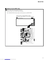
Remove FM/AM TUNER Unit and Shield R3 (five screws).
Please check SIDE A of the D.D & INPUT Assy on this status.
Note : When FM/AM TUNER Unit was removed, the product operates except FM/AM TUNER.
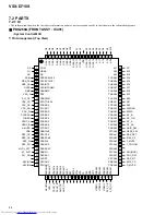
Please check IC101 mounted on SIDE B from SIDE A.
The Pin number points on SIDE A of IC 101 are shown as follows.
1
2
1
5
6
7
8
9
10
12
13
14
15
16
17
18
19
20
21
11
3
4
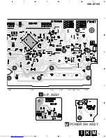
Diagnosis of D.D & INPUT Assy
D.D & INPUT Assy
A
SIDE A
Summary of Contents for VSX-D710S
Page 7: ...7 VSX D710S This page was intentionally left blank ...
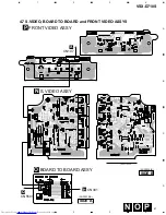
Page 17: ...VSX D710S 17 A B C D 5 6 7 8 5 6 7 8 A1 3 3 3 A ...
Page 34: ...VSX D710S 34 A B C D 1 2 3 4 1 2 3 4 A D D INPUT ASSY A IC1801 IC101 ...
Page 35: ...VSX D710S 35 A B C D 5 6 7 8 5 6 7 8 A C1801 XNP3037 A SIDE B ...
Page 37: ...VSX D710S 37 A B C D 5 6 7 8 5 6 7 8 CN102 A CN103 A R ENCODER ASSY L XNP3035 B SIDE A L K ...