background image

2

Congratulations on buying this fine Pioneer
product.
Please read through these operating instructions
so you will know how to operate your model
properly. After you have finished reading the
instructions, put them away in a safe place for
future reference.

WARNING

TO PREVENT FIRE OR SHOCK HAZ-

ARD, DO NOT EXPOSE THIS APPLIANCE TO RAIN OR
MOISTURE.

IMPORTANT

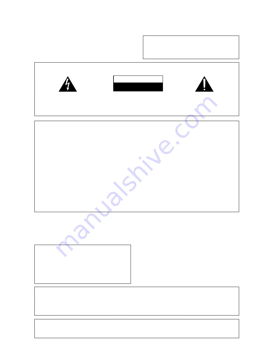
The lightning flash with arrowhead symbol,
within an equilateral triangle, is intended to
alert the user to the presence of uninsulated
"dangerous voltage" within the product's
enclosure that may be of sufficient magnitude
to constitute a risk of electric shock to persons.

The exclamation point within an equilateral
triangle is intended to alert the user to the
presence of important operating and
maintenance (servicing) instructions in the
literature accompanying the appliance.

CAUTION:
TO PREVENT THE RISK OF ELECTRIC SHOCK,
DO NOT REMOVE COVER (OR BACK).  NO
USER-SERVICEABLE PARTS INSIDE.  REFER
SERVICING TO QUALIFIED SERVICE
PERSONNEL.

RISK OF ELECTRIC SHOCK

DO NOT OPEN

CAUTION

Information to User

Alteration or modifications carried out without appropriate authorization may invalidate the user's right to
operate the equipment.

THE POWER SWITCH IS SECONDARY
CONNECTED AND THEREFORE DOES NOT
SEPARATE THE UNIT FROM MAINS
POWER IN STANDBY POSITION.

This equipment has been tested and found to comply with the limits for a Class B digital device, pursuant to Part
15 of the FCC Rules. These limits are designed to provide reasonable protection against harmful interference in
a residential installation. This equipment generates, uses, and can radiate radio frequency energy and, if not
installed and used in accordance with the instructions, may cause harmful interference to radio communica-
tions. However, there is no guarantee that interference will not occur in a particular installation. If this equip-
ment does cause harmful interference to radio or television reception, which can be determined by turning the
equipment off and on, the user is encouraged to try to correct the interference by one or more of the following
measures:

– Reorient or relocate the receiving antenna.

– Increase the separation between the equipment and receiver.

– Connect the equipment into an outlet on a circuit different from that to which the receiver is connected.

– Consult the dealer or an experienced radio/TV technician for help.

IMPORTANT NOTICE

The serial number for this equipment is located on
the  base. Please write this serial number on your
enclosed warranty card and keep it in a secure area.
This is for your security.

CAUTION:

This product satisfies FCC regulations when shielded cables and connectors are used to connect
the unit to other equipment. To prevent electromagnetic interference with electric appliances
such as radios and televisions, use shielded cables and connectors for connections.

[For Canadian model]

This Class B digital apparatus complies with
Canadian ICES-003.

[Pour le modèle Canadien]

Cet appareil numérique de la classe B est
conforme à la norme NMB-003 du Canada.

[For Canadian model]

CAUTION

: TO PREVENT ELECTRIC SHOCK DO

NOT USE THIS (POLARIZED) PLUG WITH AN EXTEN-
SION CORD, RECEPTACLE OR OTHER OUTLET UN-
LESS THE BLADES CAN BE FULLY INSERTED TO PRE-
VENT BLADE EXPOSURE.

ATTENTION

:

 POUR PREVENIR LES CHOCS

ELECTRIQUES NE PAS UTILISER CETTE FICHE
POLARISEE AVEC UN PROLONGATEUR, UNE PRISE
DE COURANT OU UNE AUTRE SORTIE DE COURANT,
SAUF SI LES LAMES PEUVENT ETRE INSERESS A
FOND SANS EN LAISSER AUCUNE PARTIE A
DECOUVERT.

Summary of Contents for VSX-D309

Page 1: ...Operating Instructions AUDIO VIDEO MULTI CHANNEL RECEIVER VSX D309 ...

Page 2: ...led and used in accordance with the instructions may cause harmful interference to radio communica tions However there is no guarantee that interference will not occur in a particular installation If this equip ment does cause harmful interference to radio or television reception which can be determined by turning the equipment off and on the user is encouraged to try to correct the interference b...

Page 3: ...where they exit from the product OUTDOOR ANTENNA GROUNDING If an outside antenna or cable system is connected to the product be sure the antenna or cable system is grounded so as to provide some protection against voltage surges and built up static charges Article 810 of the National ElectricalCode ANSI NFPA70 provides information with regard to proper grounding of the mast and supporting structur...

Page 4: ...usic or watching movies Midnight Listening Mode When late night hours or other factors require that the volume be kept low the surround effects may tend to become less than satisfactory When the midnight listening mode is on you can enjoy the effects of quality surround sound even at low volumes DVD 5 1 channel input A special 5 1 Channel input makes the VSX D309 fully compatible with Dolby Digita...

Page 5: ...ing the Remote Control Settings 22 Direct Function 22 Displays Controls 23 Front Panel 23 Display 24 Remote Control 25 Sound Modes 27 Learning about the Sound Modes 27 Switching ANALOG DIGITAL Signal Input 28 Playing a Source 28 Playing Sources with Dolby Digital or DTS Sound 29 Selecting a Sound Mode 30 Using in MIDNIGHT Listening Mode 31 Using the Tuner 32 Finding a Station 32 Tuning Directly to...

Page 6: ...ollowing supplied accessories Installing the Receiver Please note Do not place objects directly on top of this unit This would prevent proper heat dispersal When installing in a rack shelf etc be sure to leave more than 8 inches of space above the receiver 8 inches 20 cm Receiver memo MULTI CONTROL DVD LD TV SAT VCR DVR CD SOURCE CLASS MPX BAND LOUDNESS FUNCTION MUTING RECEIVER D ACCESS CHANNEL AT...

Page 7: ... other Pioneer components You can also control Pioneer components by pointing the receiver s remote control directly at the component This type of operation does not require control cords By connecting a control cord optional you can control other Pioneer equipment using this remote control unit Point the remote control unit towards the remote sensor of this unit even when operating other equipmen...

Page 8: ...t gives the best reception FM UNBAL 75Ω L R L R AM LOOP ANTENNA FM ANTENNA CD OUT CD R TAPE MD IN IN IN IN IN IN IN IN OUT CONTROL SURROUND CENTER SUB WOOFER PREOUT TO MONITOR TV VCR DVR VIDEO TV SAT DVD LD FRONT P L A Y CENTER SPEAKER SURROUND SPEAKERS FRONT SPEAKERS PCM 2 DTS DIGITAL IN COAX OPT AC OUTLET L R SUB WOOFER L R O U T R E C DVD 5 1 CH INPUT OUT Antenna snap connectors Twist the expos...

Page 9: ...elow These are analog connections When connecting equipment always make sure the power switched off and the power cord is disconnected from the wall outlet Cassette deck placement Depending on where the cassette deck is placed noise caused by leakage flux from the transformer in the receiver may occur during playback If you experience noise move the cassette deck farther away from the receiver Aud...

Page 10: ...ut formats Connections can be made from a DVD player multi channel decoder equipped with 5 1 analog outputs to the 5 1 analog inputs on this unit Always make sure that the receiver is switched off and unplugged from the wall outlet before making or changing any connections TV monitor VCR DVR etc DVD LD player Connecting Video Components Connect your video components as shown below When connecting ...

Page 11: ... of digital component DVD CD CD R etc The diagram below just gives examples of possible connections Always make sure that the receiver is switched off and unplugged from the wall outlet before making or changing any connections FM UNBAL 75Ω L R L R AM LOOP ANTENNA FM ANTENNA CD OUT CD R TAPE MD IN IN IN IN IN IN IN IN OUT CONTROL SURROUND CENTER SUB WOOFER PREOUT TO MONITOR TV VCR DVR VIDEO TV SAT...

Page 12: ...TAL IN COAX OPT AC OUTLET L R SUB WOOFER L R O U T R E C DVD 5 1 CH INPUT OUT INPUT Front left Front right Center Powered sub woofer Surround left Connecting Speakers Connect your speakers as shown below Be sure to connect each speaker to the appropriate speaker terminal and also to connect the positive and negative terminals correctly so that the same wire is connected to the positive terminal of...

Page 13: ...he TV screen CAUTION If you choose to install the center speaker on top of the TV be sure to secure it with putty or by other suitable means to reduce the risk of damage or injury resulting from the speaker falling from the TV in the event of external shocks such as earthquakes If possible install the surround speakers slightly above ear level Try not to install the surround speakers farther away ...

Page 14: ... speakers distance setting mode page 17 Use to specify the distance from your listening position to your front speaker CENTER speakers distance setting mode page 17 Use to specify the distance from your listening position to your center speaker SURROUND speakers distance setting mode page 17 Use to specify the distance from your listening position to your surround speakers Dynamic range control se...

Page 15: ...ass and set them to Large In the display F C and S refer to front center and surround speakers respectively Speaker size is denoted as L for large speakers S for small speakers and asterisk if no speaker is connected If the cone size radius of the speaker is larger than 5 inches please set to Large Switch the speaker setting mode according to the speakers you hooked up Use the or fi buttons The co...

Page 16: ...the frequency routed to the sub woofer or Large speakers We recommend setting this to 200 Hz if smaller bookshelf type speakers are used for your Small speakers Initial setting is 100 Hz If all speakers front center and surround are set to Large in SPEAKER setting mode crossover frequency cannot be set because there are no Small speakers appears in the display Press or fi to specify the crossover ...

Page 17: ...g mode the Center distance cannot be set One step equals about 1 ft Press or fi to set the distance of the CENTER speaker from the main listening position up to 30 steps SURROUND speakers distance setting mode Use to set the SURROUND speakers distance Like the CENTER speaker position the SURROUND speakers may be set in a location closer or farther than the FRONT speakers Set the distance of the SU...

Page 18: ... fi to cycle through the possible DUAL MONO settings memo Dual mono setting The dual mono setting can only be used when listening to Dolby Digital discs that have dual mono software encoded in them With this setting you can choose which channel in the dual mono setting you want to listen to Thus it is useful for soundtracks that have one language on one channel and a different language on the othe...

Page 19: ...signed to the optical input jack Initial setting is CD Press or fi to select the optical digital input 1 DVD TV CD CD R VCR or OFF After you assign the component to a digital jack like optical one whenever you select that component for example CD the receiver will automatically change to the digital input setting You can see this in the DIGITAL ANALOG indicator on the front of the receiver dB memo...

Page 20: ...ter 20 seconds Preparations Setting Up the Remote Control In addition to controlling the receiver the supplied remote control can operate your other components DVD MD VCR TV LD CD etc If your component s are listed in the Preset Code List on page 43 simply recall the corresponding preset code Recalling preset codes The following steps show you how to recall preset codes for each MULTI CONTROL butt...

Page 21: ...Some manufacturers use several sets of remote control signals and the first code may not correspond to your component Repeat steps 2 through 4 to assign preset codes for as many components as necessary 5 Press REMOTE SET UP to exit the preset mode The remote control returns to the previous operation mode When operating a PIONEER S DVD LD player set the manufacturer code to 111 in the preset mode A...

Page 22: ...ontrol the VCR and operate that component while the receiver plays a different component 1 To turn the DIRECT funtion OFF the default setting is ON press REMOTE SET UP and number button 3 at the same time 2 To turn the the DIRECT function ON if you have turned it off press REMOTE SET UP and number button 2 at the same time MULTI CONTROL DVD LD TV SAT VCR DVR CD LOUDNESS FUNCTION MUTING RECEIVER D ...

Page 23: ... various DSP modes available HALL1 HALL 2 JAZZ DANCE THEATER1 THEATER 2 and DSP off Use to create different surround sound effects from any stereo source 0 2 DTS button see pages 29 31 Use to switch between the various Dolby DTS surround modes SIGNAL SELECT button see page 28 Use to select between an analog or digital signal MASTER VOLUME Use to set the overall listening volume PHONES jack Use to ...

Page 24: ... is played DTS Lights when a source with DTS audio signals is played 9 2 DIGITAL indicator When the 2 Surround DTS mode of the receiver is on this lights to indicate playback of a Dolby Digital signal 0 CHARACTER display Shows the radio frequency or function DVD LD CD etc receiver is using OVERLOAD indicator This lights when an analog signal is too strong the SIGNAL SELECT needs to be on ANALOG It...

Page 25: ...VER D ACCESS CHANNEL ATT VOL MENU TOP MENU VOL CH 2 DSPMODE MIDNIGHT 5 1CH CD R TAPE MD CHANNEL SELECT CHANNEL LEVEL EFFECT ENTER ENTER FQ FQ ST ST FL DIMMER REMOTE SETUP MASTER VOLUME AUDIO VIDEOPRE PROGRAMMED REMOTECONTROLUNIT TV CONTROL FUNC 10 DISC SIGNAL SELECT TEST TONE RECEIVER TUNER TVCONT Î 1 2 3 4 1 4 7 8 3 5 6 7 8 9 0 2 6 8 5 1 3 0 9 7 4 DSP mode see pages 27 30 Use to put receiver in o...

Page 26: ... Use to directly access a radio station by pressing the number of the station you want 8 LOUDNESS button Use to switch on the loudness This feature is useful for getting good bass and treble sounds listening at low volumes 9 FUNCTION button Use select the playback or recording source This button lets you cycle through the different functions of the receiver in the following order CD tuner CDR TAPE...

Page 27: ...uilds a dynamic and broad sound space allowing two channel stereo signals to faithfully imitate a five speaker sound The mode should be used in conjunction with Dolby Pro Logic for sources bearing the 3 mark DSP modes The DSP Digital Signal Processing modes allow you to transform your living room into a variety of different sonic environments when playing standard two channel stereo sources Dolby ...

Page 28: ... DTS is played back with SIGNAL SELECT set in ANALOG digital noise is output caused by playing back the DTS directly no decoding To prevent noise you need to make digital connections Refer to page 11 and set SIGNAL SELECT to DIGITAL Some DVD players don t output DTS signals For more details refer to the instruction manual supplied with your DVD player Audio from a karaoke microphone and some LDs a...

Page 29: ...coding To prevent noise you need to make digital connections refer to pages 11 and set SIGNAL SELECT to DIGITAL 2 3 5 When playing LD recorded in Dolby Digital When connecting a DVD LD player or LD player using the 2 RF AC 3 output a commercially available RF demodulator RFD 1 is required The RF demodulator changes the RF signal to a digital signal which is then processed by the receiver at the di...

Page 30: ...d modes This is particularly important when using the 2 Dolby sound mode DSP mode Sound memo memo DVD 5 1CH DSP MODE 1 2 EFFECT HALL 1 HALL 2 JAZZ DANCE THEATER 2 THEATER 1 dB MULTI CONTROL DVD LD TV SAT VCR DVR CD ATT CH 2 DSPMODE MIDNIGHT 5 1CH CD R TAPE MD CHANNEL SELECT CHANNEL LEVEL EFFECT ENTER 10 DISC SIGNAL SELECT TEST TONE RECEIVER TUNER TVCONT Î 1 2 3 4 5 6 7 8 9 0 DVD 5 1CH There are tw...

Page 31: ...each Dolby DTS mode by pressing the EFFECT button The STANDARD mode cannot be changed Sound Modes memo 2 DTS Using MIDNIGHT Listening Mode When the volume is low surround effects tend to become less than satisfactory Turn the MIDNIGHT listening mode on to enjoy the effects of quality surround sound even at low volumes This mode allows you to hear effective surround sound of movies at low volume le...

Page 32: ...Q button for about a second The receiver will start searching for the next station stopping when it has found one Repeat this step to search for other stations Manual tuning To change the frequency one step at a time press the FQ FQ 5 buttons To change frequency more quickly press and hold the FQ FQ buttons until the desired frequency is reached then release MPX mode If the signal is weak or there...

Page 33: ...directly using the number buttons on the remote control this function is not available using the front panel controls of the receiver SP A STEREO TUNED Using the Tuner continues on next page 1 Press the TUNER button on the remote control Make sure the DIRECT FUNCTION is ON see p 22 2 Press the BAND button to select either FM or AM Each press switches the band between FM and AM On the receiver pres...

Page 34: ... is ON see p 22 2 Press CLASS to select the class in which the station is stored Repeatedly pressing this button cycles through the three available classes A B and C 3 Use the STATION buttons to select the station memory in which the station is stored Alternatively recall the station memory using the number buttons on the remote control If the receiver is left disconnected from the AC power outlet...

Page 35: ...onent Make sure the DIRECT FUNCTION is ON see p 22 All functions except MONITOR are accessible from the remote control On the receiver select the source directly using the front panel buttons 2 Prepare the program source Tune to the radio station load the CD etc For a video recording load the video DVD etc 3 Insert a blank tape MD video etc into the recording device connected to either CD R TAPE M...

Page 36: ...cally 2 to rewind or reverse program source 3 to fast forward program source 5 to pause program source to stop program source ENTER to play program source 5 pressed together to start recording for recording devices only Number Buttons Used to directly access tracks on a program source Button Use this button to select tracks higher than 10 like a 10 button Press this button and the remaining number...

Page 37: ...o do a rewind music search 0 TOP MENU Use this button to do a forward music search THESE CONTROLS CAN BE USED FOR DECK ONE OF A DUAL TAPE DECK 5 Press to pause the tape Press to stop the tape ENTER Press to start playback 2 Press to rewind the tape 3 Press fast forward the tape FOR DECK TWO OR ANY DECK THAT CAN RECORD 5 pressed together to start recording MULTI CONTROL DVD LD TV SAT VCR DVR CD LOU...

Page 38: ...n 6 TOP MENU Use to display the lead trailer on a DVD 7 Hold down for fast forward playback 8 1 Hold down for fast reverse playback 9 3 Press to start playback on some models pressing this when the disc tray is empty will cause the disc tray to open 0 7 Press to stop playback on some models pressing this when the disc is already stopped will cause the disc tray to open MENU Displays menus concerni...

Page 39: ... MASTER VOLUME AUDIO VIDEOPRE PROGRAMMED REMOTECONTROLUNIT TV CONTROL FUNC 10 DISC SIGNAL SELECT TEST TONE RECEIVER TUNER TVCONT Î 1 2 3 4 1 4 7 8 3 5 6 7 8 9 0 4 7 1 9 2 8 3 0 6 5 Use MULTI CONTROL buttons to put the remote control in the stated mode 7 7 Use to switch DTV audio tracks 8 3 Use to get INFO on the DTV program 9 8 Use as the GUIDE button for navigating programming 0 4 Use to choose t...

Page 40: ...ust items on the menu screen 8 NUMBER buttons Use to select channels directly 9 10 button Use to select channels higher than 10 0 EFFECT For TV and cable TV use tis button toimmediately enter a new channel CHANNEL ENTER function For satellite TV use this button to exit the menu screen MENU Use to select the menu screen TOP MENU Use to bring up the GUIDE on a satellite TV MULTI CONTROL DVD LD TV SA...

Page 41: ...is connected correctly refer to pages 8 to 12 Press MUTING on the remote control Adjust MASTER VOLUME Press the MONITOR button Press SPEAKERS to select the speakers you connected Make sure the component is connected correctly refer to pages 9 11 Press the correct function button Tune in the correct frequency Connect the antenna refer to page 8 Route 2 RF AC 3 and digital cables away from the anten...

Page 42: ...mote control Strong light such as fluorescent light is shining onto the unit s remote control signal light receiving window The FL DIMMER button is pushed Remedy Connect an outdoor antenna refer to page 8 Refer to SPEAKER setting mode on page 15 to check the speaker settings Refer to Setting the volume level of each channel on page 19 to check the speaker levels Connect the speakers refer to page ...

Page 43: ...428 429 430 431 408 414 406 434 436 408 401 404 416 417 457 458 459 408 409 420 421 422 423 424 408 407 410 425 435 412 402 418 419 411 409 441 408 432 433 402 418 419 400 Manufacturer DENON RCA PHILIPS YAMAHA JVC TEAC ONKYO MARANTZ SANYO OPTIMUS PIONEER PHILIPS PIONEER SONY TECHNICS KENWOOD TEAC DENON ONKYO YAMAHA JVC FISHER RCA OPTIMUS PIONEER SONY KENWOOD SHARP TEAC ONKYO DENON PIONEER RCA ZENI...

Page 44: ...vity Impedance VCR DVR DVD LD TV SAT 1 Vp p 75 Ω Output Level Impedance VCR DVR MONITOR 1 Vp p 75 Ω Frequency Response VCR DVR MONITOR 5 Hz to 7 MHz dB Signal to Noise Ratio 55 dB Cross Talk 55 dB FM Tuner Section Frequency Range 87 5 MHz to 108 MHz Usable Sensitivity Mono 13 2 dBf IHF 1 3 µV 75 Ω 50 dB Quieting Sensitivity Mono 20 2 dB Stereo 38 6 dBf Signal to Noise Ratio Mono 73 dB at 85 dBf St...

Page 45: ...georlossinthefuture After all wewant you listeningfor a lifetime EST 1924 EIA E L E C T R O NIC INDU S T R I E S A S S O C I A T I O N We Want You LISTENING For A Lifetime We Want You Listening For A Lifetime Used wisely your new sound equipment will provide a lifetime of fun and enjoyment Since hearing damage from loud noise is often undetectable until it is too late this manufacturer and the Ele...

Page 46: ...46 ...

Page 47: ...47 ...

Page 48: ... parts operating instructions service manuals or accessories please call the number shown below PIONEER CORPORATION 4 1 Meguro 1 Chome Meguro ku Tokyo 153 8654 Japan PIONEER ELECTRONICS USA INC P O BOX 1540 Long Beach California 90801 1540 U S A PIONEER ELECTRONICS OF CANADA INC 300 Allstate Parkway Markham Ontario L3R OP2 Canada PIONEER ELECTRONIC EUROPE N V Haven 1087 Keetberglaan 1 9120 Melsele...

Reviews: