9
VSX-519V-K
5
6
7
8
5
6
7
8
A
B
C
D
E
F
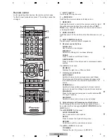
Remote control
As for operating other devices, the remote control codes
for the Pioneer products are preset. The settings cannot be
changed.
1 INPUT
SELECT
Use to select the input source.
2
RECEIVER
Switches the receiver between standby and on.
3 RECEIVER
Switches the remote to control the receiver (used to select
the white commands above the number buttons (TEST
TONE, etc)). Also use this button to set up surround sound
or Audio parameters.
4 ZONE
2
ON/OFF
Switches zone 2 of the multi-zone function between on and
off.
5 MULTI
CONTROL
buttons
Press to select control of other components.
6 Receiver
control
buttons
SIGNAL SEL
Use to select an input signal.
MIDNIGHT
Switches to Midnight or Loudness listening.
PHASE
Press to switch on/off Phase Control.
S.RETRIEVER
Press to restore CD quality sound to compressed audio
sources.
Press BD fi rst to access:
BD MENU
Displays the disc menu of Blu-ray Discs.
7 Listening
mode
buttons
AUTO/DIRECT
Switches between Auto surround mode and Stream
Direct playback. Stream Direct playback bypasses the
tone controls for the most accurate reproduction of a
source.
STEREO/A.L.C.
Switches between stereo playback, Auto level control
stereo mode and Front Stage Surround Advance modes.
STANDARD
Press for Standard decoding and to switch between
Pro Logic II options.
ADV SURR
Switches between the various surround modes.
8
System Setup and Component control buttons
The following button controls can be accessed after you
have selected the corresponding MULTI CONTROL button
(BD, TV, etc.).
Press RECEIVER fi rst to access:
AUDIO PARAMETER
Use to access the Audio options.
SETUP
Press to access the System Setup menu.
RETURN
Confi rm and exit the current menu screen.
Press BD or DVR fi rst to access:
TOP MENU
Displays the disc ‘top’ menu of a BD/DVD.
Summary of Contents for VSX-519V-K
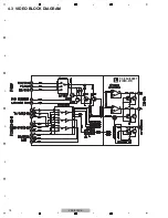
Page 18: ...18 VSX 519V K 1 2 3 4 A B C D E F 1 2 3 4 4 3 VIDEO BLOCK DIAGRAM P C B SUB ASSY VIDEO 519 L ...
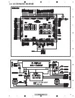
Page 19: ...19 VSX 519V K 5 6 7 8 5 6 7 8 A B C D E F 4 4 U COM BLOCK DIAGRAM P C B SUB ASSY FRONT C ...
Page 45: ...45 VSX 519V K 5 6 7 8 5 6 7 8 A B C D E F ...
Page 57: ...57 VSX 519V K 5 6 7 8 5 6 7 8 A B C D E F J CN401 M CP107 A FL FL FL SL SL SL C C C ...
Page 67: ...67 VSX 519V K 5 6 7 8 5 6 7 8 A B C D E F P 2 2 116 ...
Page 71: ...71 VSX 519V K 5 6 7 8 5 6 7 8 A B C D E F B A SIDE B B P C B SUB ASSY P T ...
Page 77: ...77 VSX 519V K 5 6 7 8 5 6 7 8 A B C D E F J 01 SIDE A SIDE B ...
Page 81: ...81 VSX 519V K 5 6 7 8 5 6 7 8 A B C D E F L SIDE A ...
Page 83: ...83 VSX 519V K 5 6 7 8 5 6 7 8 A B C D E F L SIDE B ...
Page 89: ...89 VSX 519V K 5 6 7 8 5 6 7 8 A B C D E F P N SIDE B ...

