6
En <DRB1375>
Operation
Operation
This unit is a 2-channel video selector designed to allow switching between the video output signals from two DVJ-X1 DJ DVD players.
This component is designed to allow use of a fader start signal output from a DJ mixer to perform automatic signal switching; it also
generates sync signals to help suppress image distortion when switching between video signals.
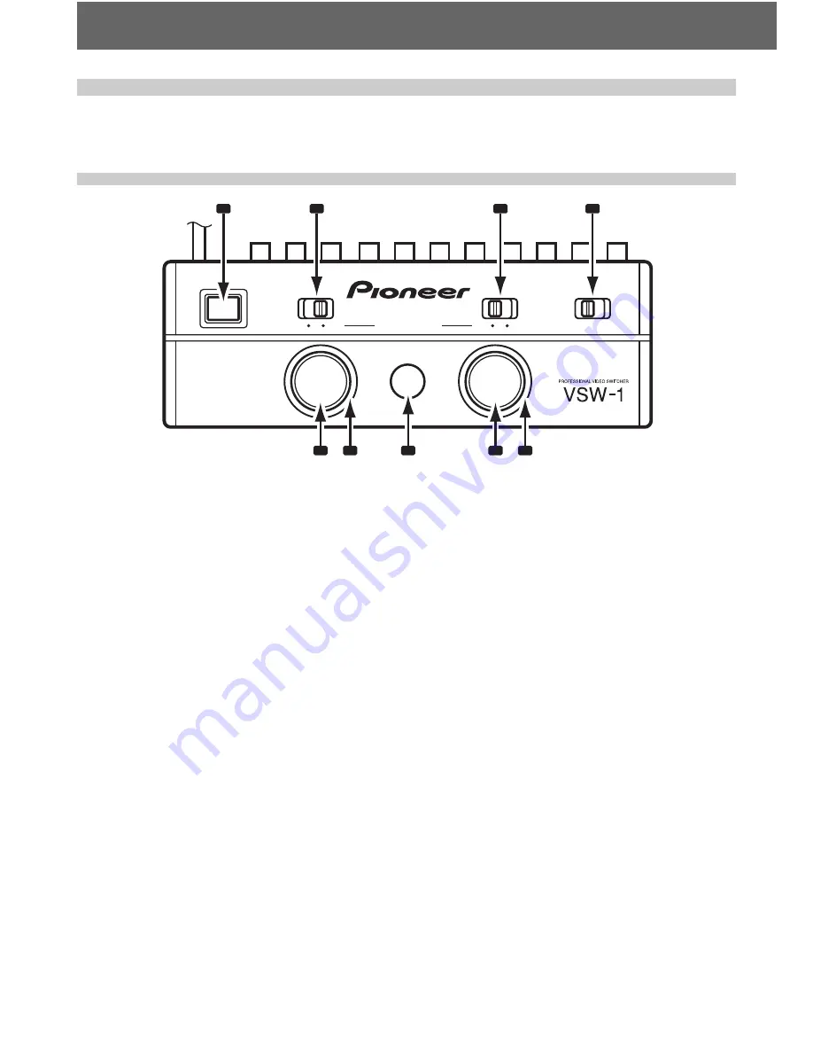
Operation Panel
B
A
VIDEO
AUTO
POWER
OFF
ON
FADER START
MODE SELECTOR
OFF
PAL
NTSC
ON
1
5
6
7
8
9
2
3
4
1. POWER button
Power is turned ON when this button is depressed to the lock posi-
tion. Press again to the unlock position to turn power OFF.
When power is first turned ON,
PLAYER A
input is selected, and the
VIDEO A
button’s outer-ring indicator lights. The
AUTO
button also
lights, indicating that the AUTO mode is selected, and the fader start
signal from the DJ mixer is used to perform automatic input selec-
tion.
2. FADER START switch A
ON:
Transmits fader start signal from DJ mixer to player A.
OFF:
Disables fader start signal from DJ mixer to player A.
3. FADER START switch B
ON:
Transmits fader start signal from DJ mixer to player B.
OFF:
Disables fader start signal from DJ mixer to player B.
4. Sync signal MODE SELECTOR switch
Selects timing for the standard sync signal generated by the unit.
PAL:
Generates sync signal conforming to PAL standard.
NTSC:
Generates sync signal conforming to NTSC standard.
Sync signal can be reacquired by resetting the position of the sync
signal
MODE SELECTOR
switch. Approximately 10 seconds are
required to reacquire sync signal.
Note:
The discs used in the two players (A and B) should be compliant with
the same signal format (PAL/NTSC). Synchronization cannot be per-
formed if the discs have differing signal formats.
5. VIDEO A button
When pressed to the ON position,
PLAYER A
input is selected, and
the ring indicator around the
VIDEO A
button lights.
Whenever power is first turned on,
PLAYER A
input is selected by
default.
If the
VIDEO B
button is pressed while holding the
VIDEO A
but-
ton depressed,
PLAYER B
input is selected; when the
VIDEO B
button is then released, input returns immediately to
PLAYER A
,
thus allowing quick switching between A/B inputs.
6. VIDEO A indicator
The indicator around the border of the
VIDEO A
button lights when
PLAYER A
input has been selected.
7. AUTO select button/indicator
When pressed to the ON position, the
AUTO
button indicator lights
and when a fader start signal is received from the DJ mixer, inputs
are switched automatically. If the
VIDEO A
or
VIDEO B
button is
pressed manually during the AUTO mode (namely, pressing which-
ever input button is not currently selected), the input will switch to
the one pressed, but the AUTO mode will continue in effect; as a
result, when a fader start signal is subsequently received from the
DJ mixer, the inputs will automatically switch once again.
When the
AUTO
button is pressed once again to the OFF condition
(button indicator goes out), the inputs will not switch even if a fader
start signal is received from the DJ mixer.
Whenever power is first turned ON, the AUTO mode is selected
by default (
AUTO
button indicator lights).
Whenever the AUTO mode is being used be sure that the DJ
mixer’s fader start switch is in the ON position.
8. VIDEO B button
When pressed to the ON position,
PLAYER B
input is selected, and
the ring indicator around the
VIDEO B
button lights.
If the
VIDEO A
button is pressed while holding the
VIDEO B
but-
ton depressed,
PLAYER A
input is selected; when the
VIDEO A
button is then released, input returns immediately to
PLAYER B
,
thus allowing quick switching between A/B inputs.
9. VIDEO B indicator
The indicator around the border of the
VIDEO B
button lights when
PLAYER B
input has been selected.


