143
VSX-49TX, VSX-47TX
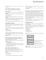
If the port becomes "L" within 3 seconds, the unit resets
automatically.
(2) Transformer temperature rise control
Valid with European and Japanese domestic models only.
European models
If the temperature at the transformer rises, the TRANS_DET port
becomes "L."
Detecting "L," the microcomputer performs the following operations:
1. System muting on
2. Protection relays off
As long as the detection port remains "L," statuses 1 and 2 are
maintained.
When the port becomes "H" (when the temperature at the transformer
drops), statuses 1 and 2 are canceled, and the unit resets automatically
(automatic reset is requested by safety regulations).
The warning indication "THERMAL" appears on the FL display.
(3) Temperature detection
Valid with North American and Japanese domestic models only.
The process mentioned in (1) is performed with European and other
general-area models.
If the temperature at the heat sink rises, the TEMP1 port becomes
"H." Detecting "H," the microcomputer performs the following
operations:
1. System muting on
2. Protection relays off
The warning indication "THERMAL" appears on the FL display.
If this status continues for more than 3 seconds, the power is turned
off (for Standby mode).
If the port becomes "L" within 3 seconds, the unit resets
automatically.
(4) Overload detection (abnormality detection)
If the speaker terminals are short-circuited or low-load driving is
detected, the OL_DET port becomes "H."
Detecting "H" in an interrupt process, the microcomputer performs
the following operations:
1. System muting on
2. All relays off (expander output off)
The expander output is turned off to perform detection during
the interrupt. As the AC relay is also turned off, no warning
indication appears on the FL display.
3. Power off (Standby mode)
(5) DC detection (defect detection)
Only DC detection is enabled 2 seconds after power-on.
If there is a fault in the power amplifier or a high-level signal lower
than5 Hz is input, the DC_DET port becomes "H."
Detecting "H," the microcomputer performs the following
operations:
1. System muting on
2. Protection relays off
The warning indication "AMP ERR" appears on the FL display.
If this status continues for more than 3 seconds, the power is turned
off (for Standby mode).
If the port becomes "L" within 3 seconds, the unit resets
automatically.
When the power is turned off owing to DC detection (also when a
user prompted by the warning indication turns off the switch on the
primary side), key inputs are disabled for 60 seconds.
The microcomputer backs up the value of the 60-second timer. The
unit will only enter Standby mode, and power will not be turned on
within 60 seconds in response to a key input after power-off on the
primary side. (When the switch on the primary side is turned on
again, key inputs will be limited for 60 seconds even if the timer
value is less than 60 seconds.)
After DC detection, power-on from the multiroom side is also
disabled for 60 seconds.
If the unit resets within 3 seconds (before the power is turned off)
after DC detection, the normal operation is restored.
(6) Diagnostic mode
This mode is only for servicing and checking the circuit design, and
not open to users.
When the DNR key and VSEL key are both held pressed for 3
seconds in Standby mode, the power is turned on, and the number
of times of each defect or abnormality detection is sequentially
displayed on the FL display.
Displayed items:
• DC detection
• Overload detection
• Fan detection
• Temperature detection
Hold the DNR key and VSEL key pressed for 3 seconds in Standby
mode.
PROTECT CHECK
DC
003
↓
PROTECT CHECK
OVER
000
↓
PROTECT CHECK
FAN
000
↓
PROTECT CHECK
TEMP
000
There is no specific mode for clearing the above-mentioned
diagnostic mode.
Diagnostic mode is only cleared with an all-reset operation.
∗
With models other than North
American models
∗
With North American and
Japanese domestic models
Summary of Contents for VSA-AX10
Page 123: ...VSX 49TX VSX 47TX 93 A B C D 1 2 3 4 1 2 3 4 L SIDE B ANALOG IN A D ASSY L ANP7390 A IC3901 ...
Page 129: ...VSX 49TX VSX 47TX 99 A B C D 1 2 3 4 1 2 3 4 Q SIDE B VR PRE OUT ASSY Q ANP7392 A ...
Page 132: ...VSX 49TX VSX 47TX 102 A B C D 1 2 3 4 1 2 3 4 R Q5814 Q5813 Q5805 IC5806 IC5807 ...
Page 195: ...VSX 49TX VSX 47TX 165 A B C D 1 2 3 4 1 2 3 4 SIDE B K1 K2 K12 K13 K18 K6 K7 EL HON GND VDD ...
Page 197: ...VSX 49TX VSX 47TX 167 A B C D 1 2 3 4 1 2 3 4 SIDE A SIDE B 7 3 2 2 PCB DIAGRAM ...


