background image


S-FCRW240B-S

4

1

2

3

4

1

2

3

4

C

D

F

A

B

E


CONTENTS


 SAFETY INFORMATION ..................................................................................................................................... 2
1. SPECIFICATIONS ............................................................................................................................................ 5
2. EXPLODED VIEWS AND PARTS LIST ............................................................................................................ 6

2.1 PACKING ................................................................................................................................................... 6
2.2 SATELLITE SPEAKER(Front, Center, Rear) ............................................................................................. 8
2.3 POWERED SUBWOOFER ........................................................................................................................ 9
2.4 POWER AMP SECTION.......................................................................................................................... 10

3. SCHEMATIC DIAGRAM ................................................................................................................................. 12

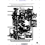
3.1 OVERALL BLOCK DIAGRAM.................................................................................................................. 12
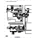
3.2 AMP and OPERATION ASSYS................................................................................................................ 14

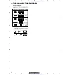
4. PCB CONNECTION DIAGRAM ..................................................................................................................... 16

4.1 AMP and OPERATION ASSYS................................................................................................................ 17

5. PCB PARTS LIST ........................................................................................................................................... 19
6. ADJUSTMENT ............................................................................................................................................... 21
7. GENERAL INFORMATION ............................................................................................................................. 22

7.1 DISASSEMBLY ........................................................................................................................................ 22

8. PANEL FACILITIES ........................................................................................................................................ 23

www. xiaoyu163. com

QQ 376315150

9

9

2

8

9

4

2

9

8

TEL 13942296513

9

9

2

8

9

4

2

9

8

0

5

1

5

1

3

6

7

3

Q

Q

TEL  13942296513  QQ  376315150  892498299 

TEL  13942296513  QQ  376315150  892498299 

http://www.xiaoyu163.com

http://www.xiaoyu163.com

Summary of Contents for S-FCRW240B-K

Page 1: ...S S W240B K THIS MANUAL IS APPLICABLE TO THE FOLLOWING MODEL S AND TYPE S Model Type Porew Requirement REMARKS S FCRW240B S KUXJI AC120V Speaker System S FCRW240B K KUXJI AC120V Speaker System S W240B S KUXJI CA AC120V Powered Subwoofer of S FCRW240B S S W240B K KUXJI CA AC120V Powered Subwoofer of S FCRW240B K For details refer to Important symbols for good services T ZZV MAR 2004 printed in Japa...

Page 2: ...sing replacement components rated for voltage wattage etc Replacement parts which have these special safety characteristics are identified in this Service Manual Electrical components having such features are identified by marking with a on the schematics and on the parts list in this Service Manual The use of a substitute replacement component which does not have the same safety characteristics a...

Page 3: ... apply the prescribed grease or glue to proper portions by the appropriate amount For replacement parts or tools the prescribed ones should be used 4 Shipping mode and shipping screws To protect the product from damages or failures that may be caused during transit the shipping mode should be set or the shipping screws should be installed before shipping out in accordance with this manual if neces...

Page 4: ... 12 3 1 OVERALL BLOCK DIAGRAM 12 3 2 AMP and OPERATION ASSYS 14 4 PCB CONNECTION DIAGRAM 16 4 1 AMP and OPERATION ASSYS 17 5 PCB PARTS LIST 19 6 ADJUSTMENT 21 7 GENERAL INFORMATION 22 7 1 DISASSEMBLY 22 8 PANEL FACILITIES 23 www xiaoyu163 com QQ376315150 9 9 2 8 9 4 2 9 8 TEL 13942296513 9 9 2 8 9 4 2 9 8 0 5 1 5 1 3 6 7 3 Q Q TEL 13942296513 QQ 376315150 892498299 TEL 13942296513 QQ 376315150 892...

Page 5: ...imensions 4 1 2 x 6 1 8 x 3 1 8 WXHXD Weight 1 2 lbs POWERED SUBWOOFER Enclosure Floor standing bass reflex type Speaker 20 cm 8 inch Power Amplifier Continuous Average Power Output is 100 Watts min at 28 ohms from 20 Hertz to 200 Hertz with no more than 1 total harmonic distortion Input 100 mV 18 kΩ at 60 Hz Sensitivity at specified frequency impedance Line level input RCA jack Crossover Frequenc...

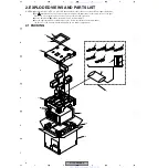
Page 6: ...of identical designation Screws adjacent to mark on product are used for disassembly For the applying amount of lubricants or glue follow the instructions in this manual In the case of no amount instructions apply as you think it appropriate NOTES 11 15 12 13 11 16 17 20 14 18 19 1 4 3 5 6 7 2 8 9 10 www xiaoyu163 com QQ376315150 9 9 2 8 9 4 2 9 8 TEL 13942296513 9 9 2 8 9 4 2 9 8 0 5 1 5 1 3 6 7 ...

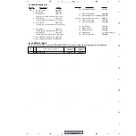
Page 7: ...Non Skid Pad for Subwoofer SEC1563 9 Non Skid Pad for Satellite SP SEC1635 10 Polyethylene Bag S0 SHL1343 11 Protection Sheet S3 SHC1806 12 Operating Instructions English SRB1334 NSP 13 Operating Instructions Assy SME3471 14 Protection Sheet S6 SHC1809 15 Protection Sheet S2 SHC1808 16 Top Protector SHA2431 17 Middle Protector SHA2432 18 Bottom Protector SHA2410 19 Packing Case See contrast table ...

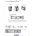
Page 8: ...ats up and the resistance rapidly increases With this function the speakers are protected from excessive input or unusual signal The resistance value increases even when using a soldering iron for repairing so allow it to cool before using Mark No Description Part No 1 Satellite Front Assy See contrast table 2 2 Satellite Center Assy See contrast table 2 3 Satellite Rear Assy See contrast table 2 ...

Page 9: ...HTP A3 3 Gasket SEC1629 4 Cosmetic Baffle Assy See contrast table 2 5 Speaker T18LU90 51P 6 Screw BYC40P180FZB Mark No Description Part No Mark No Symbol and Description S FCRW240B S KUXJI S FCRW 240B K KUXJI NSP 1 Cabinet SMM1995 SMM2001 4 Cosmetic Baffle Assy SXB1464 SXB1467 www xiaoyu163 com QQ376315150 9 9 2 8 9 4 2 9 8 TEL 13942296513 9 9 2 8 9 4 2 9 8 0 5 1 5 1 3 6 7 3 Q Q TEL 13942296513 QQ...

Page 10: ...1 21 8 3 7 7 4 10 2 12 9 18 14 VR201 parts 15 16 20 11 13 6 5 22 10 A www xiaoyu163 com QQ376315150 9 9 2 8 9 4 2 9 8 TEL 13942296513 9 9 2 8 9 4 2 9 8 0 5 1 5 1 3 6 7 3 Q Q TEL 13942296513 QQ 376315150 892498299 TEL 13942296513 QQ 376315150 892498299 http www xiaoyu163 com http www xiaoyu163 com ...
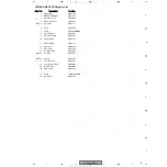
Page 11: ... L AEB7172 11 Air Packing S AEB7174 12 Rear Case AMC7039 13 Mica Sheet AEE7033 14 Vol Knob Assy PXA1621 NSP 15 Vol Knob PAC1951 NSP 16 Spring PBH1229 17 Fuse FU1 5A REK1067 18 Fuse Caution Label ARW7083 19 ICP 65 Label ARW7084 20 PBS Holder ANG7329 21 Screw IPZ30P120FMC 22 HS Holder ANG7397 www xiaoyu163 com QQ376315150 9 9 2 8 9 4 2 9 8 TEL 13942296513 9 9 2 8 9 4 2 9 8 0 5 1 5 1 3 6 7 3 Q Q TEL ...

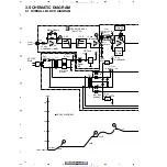
Page 12: ...dB 6dB 6dB 1 5 10 18 5dBv 50Hz 120mV IC 201 NJM2904M FU1 REK1067 5A IC 201 NJM2904M IC 41 NJM2904M IC 44 NJM7906FA IC 43 NJM7806FA D31 D34 S5688G 16v 16v D201 T11 T12 D33 D31 D32 D34 PC41 TLP621 Y JA201 2 5 7 2 1 1 Q201 2SC2412K OPERATON ASSY AWU7761 B 12 6v 12 6v 6v 6v 6 1v 0 v B A A B C C www xiaoyu163 com QQ376315150 9 9 2 8 9 4 2 9 8 TEL 13942296513 9 9 2 8 9 4 2 9 8 0 5 1 5 1 3 6 7 3 Q Q TEL ...

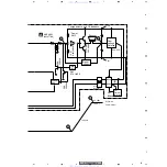
Page 13: ...Detection Ó Ó 34 5dB 34 5dBv 53 V Total Gain 53dB 50Hz IC 41 NJM2904M Q53 Q54 2SC4060 Q21 IRF640 Q55 DTA124EK D15 G3SBA20L C13 C14 Q56 2SK246 Q58 2SK246 6 7 84v 84v 168v D D E E www xiaoyu163 com QQ376315150 9 9 2 8 9 4 2 9 8 TEL 13942296513 9 9 2 8 9 4 2 9 8 0 5 1 5 1 3 6 7 3 Q Q TEL 13942296513 QQ 376315150 892498299 TEL 13942296513 QQ 376315150 892498299 http www xiaoyu163 com http www xiaoyu16...
Page 14: ... WITH SAME TYPE AND RATINGS OF FUSE CAUTION AC POWER CORD KUC PDG1064 KUC 60Hz AC120V POWER TRANSFORMER AUDIO SIGNAL SIGNAL ROUTE AWU7761 A B www xiaoyu163 com QQ376315150 9 9 2 8 9 4 2 9 8 TEL 13942296513 9 9 2 8 9 4 2 9 8 0 5 1 5 1 3 6 7 3 Q Q TEL 13942296513 QQ 376315150 892498299 TEL 13942296513 QQ 376315150 892498299 http www xiaoyu163 com http www xiaoyu163 com ...

Page 15: ...VIEWS and PARTS LIST or PCB PARTS LIST The mark found on some component parts indicates the importance of the safety factor of the part Therefore when replacing be sure to use parts of identical designation The power supply is shown with the marked box http getMANUAL com www xiaoyu163 com QQ376315150 9 9 2 8 9 4 2 9 8 TEL 13942296513 9 9 2 8 9 4 2 9 8 0 5 1 5 1 3 6 7 3 Q Q TEL 13942296513 QQ 37631...

Page 16: ...B C E B C E D G S B C E B C E B C E D G S D G S 3 The parts mounted on this PCB include all necessary parts for several destination For further information for respective destinations be sure to check with the schematic diagram 4 Viewpoint of PCB diagrams Resistor array 3 terminal regulator Capacitor Connector P C Board Chip Part SIDE B SIDE A www xiaoyu163 com QQ376315150 9 9 2 8 9 4 2 9 8 TEL 13...

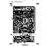
Page 17: ... C Q51 IC11IC12 Q53 Q54 Q57 IC21 Q21 Q12 Q11 Q52 Q56 Q58 IC43 IC44 VR41 To Speaker SIDE A SIDE A A B A B www xiaoyu163 com QQ376315150 9 9 2 8 9 4 2 9 8 TEL 13942296513 9 9 2 8 9 4 2 9 8 0 5 1 5 1 3 6 7 3 Q Q TEL 13942296513 QQ 376315150 892498299 TEL 13942296513 QQ 376315150 892498299 http www xiaoyu163 com http www xiaoyu163 com ...
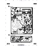
Page 18: ...IC202 IC201 Q71 Q22 Q23 Q72 Q31 Q201 IC51 IC41 Q55 SIDE B SIDE B A B A B www xiaoyu163 com QQ376315150 9 9 2 8 9 4 2 9 8 TEL 13942296513 9 9 2 8 9 4 2 9 8 0 5 1 5 1 3 6 7 3 Q Q TEL 13942296513 QQ 376315150 892498299 TEL 13942296513 QQ 376315150 892498299 http www xiaoyu163 com http www xiaoyu163 com ...

Page 19: ...K Q21 IRF640 D52 D55 11EQS06 D23 D53 1SS133 D26 20E2 FC D35 DAN217 D15 G3SBA20L D17 D18 D37 MTZJ15A D21 MTZJ18B D25 MTZJ20A D36 MTZJ6 2B D27 MTZJ6 8B D101 D104 D16 D24 D28 S5688G D31 D34 D51 S5688 TH22 AEX7005 PC41 TLP621 COILS AND FILTERS L1 LINE FILTER ATF 151 TRANSFORMERS T12 ATT7058 T11 ATT7059 CAPACITORS C2 0 033 250 ACE7023 C13 C14 2200 100 ACH7140 C19 C20 CCCSL470K2H C42 C45 CEAT100M50 C224...

Page 20: ...S1 10S J OTHERS 4P CABLE HOLDER 51048 0400 J201 JUMPER WIRE D20PYY0425E JA201 1P JACK VKB1077 Mark No Description Part No www xiaoyu163 com QQ376315150 9 9 2 8 9 4 2 9 8 TEL 13942296513 9 9 2 8 9 4 2 9 8 0 5 1 5 1 3 6 7 3 Q Q TEL 13942296513 QQ 376315150 892498299 TEL 13942296513 QQ 376315150 892498299 http www xiaoyu163 com http www xiaoyu163 com ...
Page 21: ... Attenuator 4 Low frequency oscillator 7 7 7 7 7 GAIN Adjustment 1 Decrease the level of the Adjustment Variable resistors VR for the channel to adjusted 2 Increase LEVEL VOLUME maximum 3 Adjust GAIN VR41 volume Apply the signal to the Line IN of JA201 As the gain from IN to SPEAKER OUT 53dB freq 50 Hz input of 10mVrms to Input results in output of 0 72 W 4 5Vrms 28 W at SPEAKER OUT After power su...

Page 22: ... To detach it pry it open by inserting a flat blade screwdriver into bottom slot between the cabinet and front panel SPEAKER To detach first remove the front panel then remove the 4 external screws 2 SATELLITE Satellite Speakers are provided as assembly units Removing the Operation Panel Screw1 Screw2 AMP ASSY A OPERATION ASSY B Operation Panel www xiaoyu163 com QQ376315150 9 9 2 8 9 4 2 9 8 TEL 1...

Page 23: ...ifier and speaker will be clipped when the output of the amplifier or receiver is inc reased with the subwoofer level set to MAX 3 LINE LEVEL IN Connect SUBWOOFER OUTPUT terminal of the receiver to this terminal with the supplied RCA cable If the output of the receiver connected to this unit is high or if the output has a low range boosted by the Bass control Bass boost or other means there may be...

Reviews: