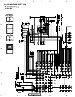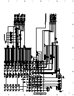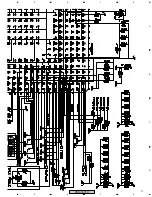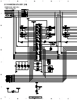
8
A
B
C
D
1
2
3
4
1
2
3
4
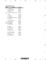
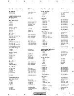
PRO-507PU
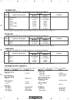
SEMICONDUCTORS
IC7703
AGC1027
[8620 BLOCK(U)]
SEMICONDUCTORS
IC7601
EM8620L-LFC
MISCELLANEOUS
F 7601,7602
ATX1066
X 7601
ASS1208
RESISTORS
R 7646,7647
RS1/16SS1400F
R 7649-7651
RAB4CQ330J
R 7652-7654
RAB4CQ103J
Other Resistors
RS1/16SS###J
• HN MODULE ASSY (AWV2311)
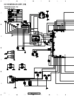
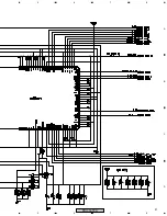
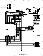
Note: For Schematic Diagram and PCB Connection Diagram. Refer to “ 2.4 - 2.9 Schematic Diagram and 3. PCB Connection Diagram”
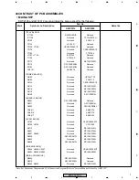
• TANSHI ASSY
AWW1153 and AWW1156 are constructed the same except for the following :
Mark
Symbol and Description
Part No.
AWW1156
AWW1153
Remarks
R8842, R8910
RS1/16SS0R0J
Not used
R8843
Not used
RS1/16SS0R0J
JA8801
AKB1338
AKB1343
JA8803, JA8805
AKB1331
AKB1341
JA8807
AKB1334
AKB1344
JA8808, JA8809
AKB1332
AKB1342
JA8810
Not used
AKN7008
• POD ASSY
Mark
Symbol and Description
Part No.
AWW1154
AWW1158
Remarks
R9200
RS1/16SS0R0J
Not used
R9201
Not used
RS1/16SS0R0J
AWW1158 and AWW1154 are constructed the same except for the following :
• SIDE ASSY
Mark
Symbol and Description
Part No.
AWW1157
AWW1155
Remarks
R9141
RS1/16SS0R0J
Not used
R9142
Not used
RS1/16SS0R0J
JA9101
AKB1303
AKB1304
JA9102
AKB1305
AKB1306
AWW1155 and AWW1157 are constructed the same except for the following :
Note: For Schematic Diagram and PCB Connection Diagram. Refer to “Service Manual: Order No. ARP3355”
Note: For Schematic Diagram and PCB Connection Diagram. Refer to “Service Manual: Order No. ARP3355”
Note: For Schematic Diagram and PCB Connection Diagram. Refer to “Service Manual: Order No. ARP3355”
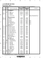
Mark No.
Description
Part No.
Mark No.
Description
Part No.
CAPACITORS
C 7601-7609
DCH1201
C 7610,7611
CCSSCH7R0D50
C 7612,7613,7615-7639
CKSSYF104Z16
[8620 DDR BLOCK(U)]
SEMICONDUCTORS
IC7701,7702
EDD2516AKTA-6B
MISCELLANEOUS
F 7701
ATL7002
RESISTORS
R 7709,7710
RS1/16SS1001F
R 7711-7718
RAB4CQ560J
Other Resistors
RS1/16SS###J
Summary of Contents for PRO-507PU
Page 15: ...15 A B C D 5 6 7 8 5 6 7 8 PRO 507PU ...
Page 17: ...17 A B C D 5 6 7 8 5 6 7 8 PRO 507PU ...
Page 19: ...19 A B C D 5 6 7 8 5 6 7 8 PRO 507PU ...
Page 20: ...20 A B C D 1 2 3 4 1 2 3 4 PRO 507PU 2 6 HN MODULE ASSY 3 6 ETHERNET BLOCK HN MODULE ASSY 3 6 ...
Page 21: ...21 A B C D 5 6 7 8 5 6 7 8 PRO 507PU ...
Page 22: ...22 A B C D 1 2 3 4 1 2 3 4 PRO 507PU 2 7 HN MODULE ASSY 4 6 HNM USB BLOCK HN MODULE ASSY 4 6 ...
Page 23: ...23 A B C D 5 6 7 8 5 6 7 8 PRO 507PU USB POWER SECTION ...
Page 24: ...24 A B C D 1 2 3 4 1 2 3 4 PRO 507PU 2 8 HN MODULE ASSY 5 6 HNM IO BLOCK HN MODULE ASSY 5 6 ...
Page 25: ...25 A B C D 5 6 7 8 5 6 7 8 PRO 507PU ...
Page 27: ...27 A B C D 5 6 7 8 5 6 7 8 PRO 507PU For Power Sequence ...
Page 29: ...29 A B C D 5 6 7 8 5 6 7 8 PRO 507PU HN MODULE ASSY SIDE B ANP2148B ...
Page 34: ...34 A B C D 1 2 3 4 1 2 3 4 PRO 507PU Block Diagram ...
Page 35: ...35 A B C D 5 6 7 8 5 6 7 8 PRO 507PU ...
Page 36: ...36 A B C D 1 2 3 4 1 2 3 4 PRO 507PU ...
Page 37: ...37 A B C D 5 6 7 8 5 6 7 8 PRO 507PU ...

